background image

HRK3-HB-5


V

IA

L

ITE

HD


3U

 CHASSIS 

H

ANDBOOK


29 

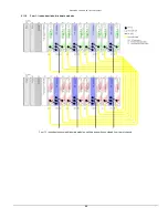
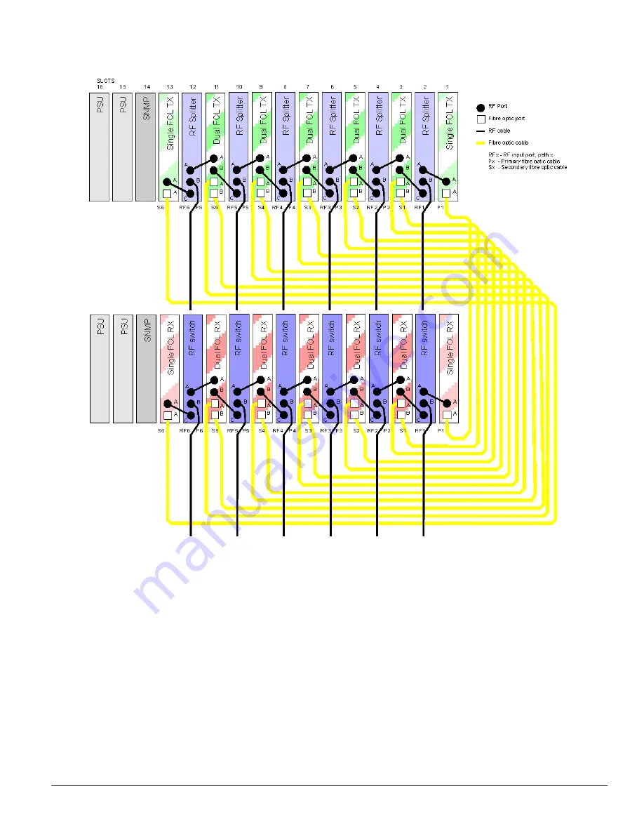
6.11.10  Six 1:1 redundant links, blindmate modules 


Six 1:1 redundant links using blindmate modules, splitters and switches, viewed from rear of chassis 


Содержание HPS-3

Страница 1: ... 3U chassis User Manual HRK3 HB 5 CR3274 17 12 14 Pulse Power Measurement Ltd 65 Shrivenham Hundred Business Park Watchfield Swindon Wiltshire SN68TY UK Tel 44 0 1793 784389 Fax 44 0 1793 784391 Email sales ppm co uk Web www vialite com ...

Страница 2: ...he ViaLiteHD chassis is not equipped with any active electronics but it may be fitted with them Precautions for handling electro static sensitive devices should be observed when handling all ViaLiteHD modules Technicians should ensure that they use effective personal grounding i e ESD wrist strap etc when servicing the equipment Any equipment or tools used should be grounded to prevent static char...

Страница 3: ...cy load module front panel 17 5 3 3 Redundancy load module DIP switches 17 5 3 4 Redundancy load module setting the load DIP switches 18 5 3 5 Redundancy load module using with SNMP and controller module 18 5 4 Power Supply HPS CS 3 for use with OEM modules HRx xx xM xx 18 6 INSTALLATION GUIDE 20 6 1 Chassis Installation 20 6 2 6HP Power Supply Module Installation slots 15 and 16 20 6 3 5HP Standa...

Страница 4: ...HRK3 HB 5 VIALITEHD 3U CHASSIS HANDBOOK 4 9 PRODUCT WARRANTY 34 10 FCC APPROVAL 34 ...

Страница 5: ...The range is ideal for permanent and semi permanent installation in Satellite communications GPS antenna remoting and other related applications The variety of links available includes low frequency timing 2kHz to wideband RF 4 2GHz RF splitters amplifiers and switches they also include a full suite of supporting functions including RS232 422 485 Ethernet and control systems to monitor and control...

Страница 6: ...tems Listed below is a brief summary of inter family compatibility RF Compatible optical and RF interfaces RF digital Compatible optical and RF interfaces RS232 Compatible optical and digital interfaces RS422 Compatible optical and digital interfaces RS485 Compatible optical and digital interfaces Ethernet Modules of matching speed have compatible optical and digital interfaces Redundancy Switch C...

Страница 7: ...SI 3 connector on the rear panel of the chassis This connector also has the interface for the summary alarm relay if a module has been fitted to provide this function This permits the integration of the ViaLiteHD equipment into a Maintenance Control system All of the module external power connections LNA feeds and chassis backplane external power connections are routed to a second SCSI 3 connector...

Страница 8: ...s short circuited to ground by the module If the module enters an alarm state the alarm pin is released to a high impedance state and current is no longer drawn from the constant current source In the case of a positive voltage and pull up resistor the voltage on the alarm output pin will rise to indicate the alarm state It follows that if a module is removed from the chassis the alarm will be rai...

Страница 9: ...nvironmental specification when operating in a typical configuration A typical configuration is all modules populated 13 Transceiver 1 SNMP 2 PSU chassis power consumption 67 watts no external DC power input or DC output and no obstruction to convection air path Under normal operating conditions module slots 1 14 are cooled by convection module slots 15 and 16 are force air cooled with exhaust at ...

Страница 10: ...gn to permanently hold the blanking panel in position HPS 0 ViaLiteHD Blank Panel 6HP 4 7 Minimum power supply load If the chassis power supplies are operating in dual redundant configuration there should be a minimum load of 12 watts to ensure that both power supplies are active below this level one power supply may be in idle mode its LED will not be illuminated If necessary a redundancy load mo...

Страница 11: ...entrates the alarms from each module to a common point Open Drain alarm 1 per 5 7HP slot Power Good 2 per 6 HP slot Analogue Monitor 2 per 5 HP slot Ground Type 50 way connector Har mik female SCSI 3 Power Concentrator Connector J4 SCSI 3 This concentrates the power connections and summary alarms to a common point 12Vdc backplane power Ground Current sharing bus Summary Alarm relay optional Extern...

Страница 12: ...ial number below and including SN1221901 Pin Out J19 to J31 Module Data connectors Pin Slot data Pin Slot data Pin Slot data 1 GND 4 TX_232_IN 7 RX_422_OUT 2 TX_422_IN 5 GND 8 RX_232_OUT 3 TX_422_IN 6 RX_422_OUT 9 RTS_485 Note Data on the connector is only for the module fitted in that 5HP slot and is printed beneath J19 slot 1 J20 slot 2 J31 Slot 13 Connections in Blue text are optional and only ...

Страница 13: ...d_A_X or the LNA or BUC feed is connected to it will match with the connector letter on the rear panel Channel A is the upper channel and channel B is the lower channel Transceivers always have the receiver as the upper channel and the transmitter as the lower channel The LNA and BUC feed will only be connected if the module in the slot has the appropriate functionality J4 pin assignment for a tra...

Страница 14: ...rocedure Disconnect the fan power connector J32 Using a magnetic screw driver remove the two screws fixing the fan cassette Withdraw the fan cassette The fan is replaced by the following procedure Insert the fan cassette Using a magnetic screw driver fix the cassette in place using the two screws provided Connect the fan power connector J32 NOTE The FAN connector is polarised match the slot in the...

Страница 15: ...n ambient temperature of 40 C The HPS power supply has a wide range alternating current AC input and can operate from 110V and 230V nominal mains supplies Mains power is applied at the rear of the chassis via an earthed IEC60320 connector and regulated direct current DC power is supplied to the chassis backplane PCB for distribution to the plug in modules This connector is also used for reporting ...

Страница 16: ...tter 3 2 W 4 0W 6 0 Typical per slot at 25 50 70 C laser types D E and K excluding LNA LNB power Single Receiver 1 5 W Typical per slot Dual Transmitter 4 0 W Typical per slot excluding LNA LNB power Dual Receiver 2 6 W Typical per slot Transceiver 3 3 W Typical per slot excluding LNA LNB power Amplifier 2 4W Typical per slot Serial Digital 0 7W Typical per slot Switch 0 4W Typical per slot Splitt...

Страница 17: ... load plug in module has two front panel LEDs for indication of the state of the module The following table shows the operation Colour SNMP and Web controller LED1 GREEN Normal No light No power LED2 GREEN LOAD ON Any load resistor active No light LOAD OFF 5 3 3 Redundancy load module DIP switches The ViaLiteHD Redundancy load module has one four way DIP switch SW5 that configures the load The swi...

Страница 18: ... with OEM modules HRx xx xM xx The HPS CS 3 is a Panel Mounting 12V DC output mains input supply with a 15 way Molex connector for connection to ViaLiteHD OEM modules HRx xx xM xx HPS CS 3 Description Wide input range AC power supply Dimensions external W x H x D 90 45 32 mm supplied with mounting bracket Lead length 1700mm typical Weight 0 2kg Input Supply Power 110V or 230V nominal at 50 60Hz 90...

Страница 19: ...HRK3 HB 5 VIALITEHD 3U CHASSIS HANDBOOK 19 HPS CS 3 with supplied mounting bracket power lead not shown ...

Страница 20: ...guide applying pressure via the handle you may also apply pressure just above the LED Avoid applying pressure on the ventilation grill As the module is fully mated the top of the handle should snap back and lock in position The pawls of the handle should be fully engaged in the matching slots To remove a 6HP power supply module Push the release button of the module handle down and simultaneously p...

Страница 21: ...riv Number 1 screwdriver Push the release button of the module handle down and simultaneously pull the top of the handle forwards Remove the protective cover from the modules optical connectors and clean any optical connectors Align the module upright and perpendicular to the front face of the chassis so that the PCB slides into the crow s feet card guides top and bottom Gently push the module dow...

Страница 22: ...o the front face of the chassis so that the PCB slides into the crow s feet card guides top and bottom Gently push the module down its guide applying pressure via the handle you may also apply pressure between the LED and test connector As the module is fully mated the top of the handle should snap back and lock in position The pawls of the handle should be fully engaged in the matching slots If p...

Страница 23: ... above and below the slot on the chassis top and bottom rails Firmly push the panel in until you feel the barbs click To remove the blanking panel Pull the blanking panel towards you it may be necessary to use extra leverage Discard the panel as the plastic barbs will now be over stressed and will not provide a reliable fixing 6 8 6HP blanking panel installation slots 15 16 Blanking panels should ...

Страница 24: ...uplexed 1 BNC 75ohms 1 SC APC PPM part number 85071 ViaLiteHD Chassis plate Blindmate 1 BNC 50ohms 1 SC APC PPM part number 85072 ViaLiteHD Chassis plate Blindmate 2 BNC 50ohms 2 SC APC PPM part number 85073 ViaLiteHD Chassis plate Blindmate 2 SC APC 6 10 Electrical power connection Power should be applied to the chassis with the supplied power cords AC chassis only if these are not used a suitabl...

Страница 25: ...ndant transmitters standard modules The blank slot can be used as a storage slot for a hot spare Four 1 1 redundant transmitters using standard plug in modules and splitters viewed from rear of chassis 6 11 2 Four 1 1 redundant transmitters blindmate modules The blank slot can be used as a storage slot for a hot spare Four 1 1 redundant transmitters using blindmate plug in modules and splitters vi...

Страница 26: ... 1 redundant receivers standard modules The blank slot can be used as a storage slot for a hot spare Four 1 1 redundant receivers using standard plug in modules and switches viewed from rear of chassis 6 11 6 Four 1 1 redundant receivers blindmate modules The blank slot can be used as a storage slot for a hot spare Four 1 1 redundant receivers using blindmate plug in modules and switches viewed fr...

Страница 27: ...ewed from rear of chassis A A A A B C A B A B C A A B B A B C A A B B A B C A A B B A B C A A B PSU PSU SNMP SLOTS 16 15 14 13 12 11 10 9 8 7 6 5 4 3 2 1 B A A A A A B C A A B S6 RF6 P6 S5 RF5 P5 S4 RF4 P4 S3 RF3 P3 S2 2 P2 S1 P1 RF RF1 Dual FOL RX Dual FOL RX Dual FOL RX Dual FOL RX Dual FOL RX Single FOL RX Single FOL RX RF switch RF switch RF switch RF switch RF switch RF switch RF Port Fibre o...

Страница 28: ...HRK3 HB 5 VIALITEHD 3U CHASSIS HANDBOOK 28 6 11 9 Four 1 1 redundant links blindmate modules Four 1 1 redundant links using blindmate modules splitters and switches viewed from rear of chassis ...

Страница 29: ...HRK3 HB 5 VIALITEHD 3U CHASSIS HANDBOOK 29 6 11 10 Six 1 1 redundant links blindmate modules Six 1 1 redundant links using blindmate modules splitters and switches viewed from rear of chassis ...

Страница 30: ...r view Vibration applied to the system Vibration Sinusoidal Planes 3 planes X Y Z Severity 5G 25 2000 Hz 1 octaves per minute Duration 1 2 hour in each axis Standard IEC68 2 6 1982 Shock applied to the system Shock half sine Axis 6 axis X X Y Y Z Z Severity 15g 11ms Shock half sine Duration 3 shocks each direction of each axes Standard IEC68 2 27 1987 A continuous wave RF test signal was applied t...

Страница 31: ...ation Sample plot of vibration in Y axis Sample plot of Half Sine Shock in Y axis No measureable change in RF power level was detected The system under test passed all the vibration and shock tests detailed above A full test report is available contact ViaLite Communications for more details ...

Страница 32: ...HRK3 HB 5 VIALITEHD 3U CHASSIS HANDBOOK 32 7 Part Numbering 7 1 ViaLiteHD Chassis part numbering 7 2 ViaLiteHD Power supply part numbering ...

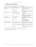
Страница 33: ...Fan power disconnected Check fan power connector is inserted Replace failed fan Difficulty inserting module Incorrect alignment Incorrect module slot Check that the module is correctly fitted in the card guides Check that module is in correct slot Slots 1 13 for 5HP modules Slot 14 for 7 HP modules Slot 15 16 for 6 HP modules Summary alarm triggered when no module failure is indicated Summary alar...

Страница 34: ...dent misuse neglect wilful act or default or any cause other than normal use Claims must be made promptly and during the warranty period IMPORTANT Please contact both your selling agent and ViaLite Communications prior to returning any goods for Warranty or Non Warranty repairs Goods will not be accepted without a valid Goods Return Number GRN 10 FCC Approval Information to the user of ViaLiteHD p...

Отзывы: