HRK3-HB-5
V
IA
L
ITE
HD
3U
CHASSIS
H
ANDBOOK
20
6
Installation Guide
6.1
Chassis Installation
The
ViaLiteHD
Power Supply Modules do not have an isolating switch on the mains voltage inlet. For this reason, the
ViaLiteHD
Chassis
must be installed within easy reach of a clearly labelled dual pole mains isolation switch, which supplies the equipment.
The
ViaLiteHD
19” chassis is designed to fit 19” racks and occupies a height of 3U. The chassis is provided with flanges for mounting to the
rack. The Chassis backplane contains 9-way D-type data connectors for each module position. This provides user access to data
connections from relevant modules (depends on module type). The pin outs of these connectors depend on the type of module in use in that
chassis posit
ion. There is also an “Alarm concentration” connector providing access to alarms and monitoring information from all modules
and a “Power Concentration” connector that provides access to various power feeds and the summary alarm.
6.2
6HP Power Supply Module Installation (slots 15 and 16)
The
ViaLiteHD
Power Supply Module powers the plug-in modules via the Chassis backplane PCB. It occupies slots 15 and 16.
To install a 6HP power supply module
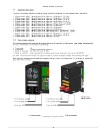
Push the release button of the module handle down and simultaneously pull the top of the handle forwards.
Align the module upright and perpendicular to the front face of the chassis
so that the PCB slides into the “straight” card guides top and
bottom.
Gently push the module down its guide, applying pressure via the handle; you may also apply pressure just above the LED. Avoid
applying pressure on the ventilation grill.
As the module is fully mated the top of the handle should snap back and lock in position.
The pawls of the handle should be fully engaged in the matching slots.
To remove a 6HP power supply module
Push the release button of the module handle down and simultaneously pull the top of the handle forwards.
Apply pressure via the handle and gently withdraw the module from the chassis.
6.3
5HP Standard Plug-in Modules (slots 1-13)
All
ViaLiteHD
plug-in modules are hot-swappable, so it is not necessary to power-down the chassis before inserting a module. All standard
optical connectors are retained by the module. So it will be necessary to either disconnect any cables or have a sufficiently long service loop.
To install a 5HP Standard module and matching interface plate
The protective covers on the connectors may be left in place.
Push the release button of the module handle down and simultaneously pull the top of the handle forwards.
Alig
n the module upright and perpendicular to the front face of the chassis so that the PCB slides into the “crow’s feet” card guides top
and bottom.
Gently push the module down its guide, applying pressure via the handle, you may also apply pressure between the LED and test
connector.
As the module is fully mated the top of the handle should snap back and lock in position.
The pawls of the handle should be fully engaged in the matching slots.
If power is applied to the chassis the module power LED should light as soon as the module is fully inserted
Remove protective covers and connect any interface cables


