background image


2


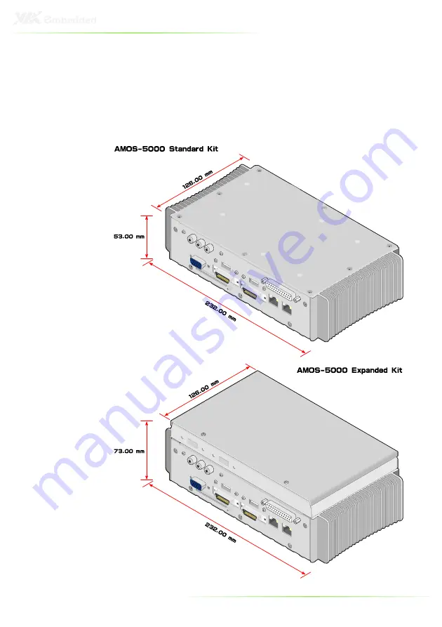
The AMOS-5000 is a fanless and compact chassis kit that 
complements the EITX-3000. The AMOS-5000 comes in two 
configurations: standard and expanded storage.  

The standard AMOS-5000 configuration consists of front and rear 
I/O plates and a top cover. The expanded storage configuration 
consists of front and rear I/O plates and a compartmentalized 
storage section that can support up to two 2.5” disk drives. 


Содержание AMOS-5000

Страница 1: ...user manual AMOS 5000 Fan less compact embedded chassis kit for the EITX 3000 Revision 1 00 100 11032009 1551...

Страница 2: ...s the right the make changes to the products described in this manual at any time without prior notice Regulatory Compliance FCC A Radio Frequency Interference Statement This equipment has been tested...

Страница 3: ...ns arises get the equipment checked by authorized service personnel o The power cord or plug is damaged o Liquid has penetrated into the equipment o The equipment has been exposed to moisture o The eq...

Страница 4: ...er 1 x CF cover 1 x package of cable ties 1 x audio cable 1 x GPIO cable 1 x package of chassis screws AMOS 5000 1MSZA1 Expanded storage kit 1 x front I O panel 1 x rear I O panel 1 x top half of stor...

Страница 5: ...talling the standard kit 14 Installing the front I O plate 15 Installing the rear I O plate 17 Installing the top cover 19 Installing the hard drive 19 Installing the WLAN module 20 Installing the top...

Страница 6: ...1 1 Overview...

Страница 7: ...es in two configurations standard and expanded storage The standard AMOS 5000 configuration consists of front and rear I O plates and a top cover The expanded storage configuration consists of front a...

Страница 8: ...r two USB ports four COM ports one GPIO port one DC in port two LED indicators and one WLAN antenna The rear I O plate features cutouts for three TRS jacks one VGA port two USB ports two LVDS ports on...

Страница 9: ...n 2 x USB 4 x COM 1 x antenna 2 x LED 1 x GPIO 1 x DC in 2 x USB 4 x COM 1 x antenna 2 x LED Rear I O support 3 x TRS jack 1 x VGA 1 x CF 2 x USB 2 x LVDS 2 x LAN 1 x LPT 3 x TRS jack 1 x VGA 1 x CF 2...

Страница 10: ...nsing 10 90 45 C non condensing Vibration resistance With CF With CF With CF With CF 5 Grms IEC 60068 2 64 random 5 500 Hz 1 Oct min 1 hr axis With HDD With HDD With HDD With HDD 1 Grms IEC 60068 2 64...

Страница 11: ...6 2 Installing the I O cables...

Страница 12: ...he GPIO cable Step 1 Step 1 Step 1 Step 1 Break off the GPIO cutout filler Step 2 Step 2 Step 2 Step 2 Use a metal file to smooth out any rough edges Step 3 Step 3 Step 3 Step 3 Insert the 9 pin D sub...

Страница 13: ...8 Step 4 Step 4 Step 4 Step 4 Fasten the standoff screws to secure the connector to the front I O plate...

Страница 14: ...9 Installing the WLAN antenna Step 1 Step 1 Step 1 Step 1 Insert the WLAN antenna port into the antenna cutout Step Step Step Step 2 2 2 2 Fasten the WLAN antenna port in place with the nut...

Страница 15: ...BLES Installing the TRS audio cable Ste Ste Ste Step 1 p 1 p 1 p 1 Insert the 3 jack TRS connector into the TRS cutout Step Step Step Step 2 2 2 2 Fasten the standoff screws to secure the connector to...

Страница 16: ...nstalling the USB I O cable Step 1 Step 1 Step 1 Step 1 Insert the USB connectors into the USB cutouts Step Step Step Step 2 2 2 2 Fasten the standoff screws to secure the connectors to the rear I O p...

Страница 17: ...ble Step 1 Step 1 Step 1 Step 1 Break off the LPT cutout filler Step 2 Step 2 Step 2 Step 2 Use a metal file to smooth out any rough edges Step 3 Step 3 Step 3 Step 3 Insert the 25 pin D sub LPT conne...

Страница 18: ...13 St St St Step 4 ep 4 ep 4 ep 4 Fasten the standoff screws to secure the connector to the rear I O plate...

Страница 19: ...14 3 Installing the standard kit...

Страница 20: ...15 INSTALLING THE FRONT I O PLATE Step 1 Step 1 Step 1 Step 1 Remove all standoff screws from the front I O connectors of the EITX 3000...

Страница 21: ...p Step Step 2 2 2 2 Align the front I O plate with EITX 3000 Step Step Step Step 3 3 3 3 Secure the front I O plate to the heatsink of the EITX 3000 And reinstall all standoff screws to the front I O...

Страница 22: ...7 INSTALLING THE REAR I O PLATE Step 1 Step 1 Step 1 Step 1 Remove all standoff screws from the rear I O connectors of the EITX 3000 Step Step Step Step 2 2 2 2 Align the rear I O plate with EITX 3000...

Страница 23: ...p Step Step 3 3 3 3 Secure the rear I O plate to the heatsink of the EITX 3000 And reinstall all standoff screws to the rear I O connectors Step Step Step Step 4 4 4 4 Install the CF cover on the rear...

Страница 24: ...isk brackets on the 2 5 inch hard disk drive And insert the rubber shock absorbers to the HDD mounting brackets Step Step Step Step 2 2 2 2 Flip the top cover over and align the shock absorbers over t...

Страница 25: ...WLAN module Step 1 Step 1 Step 1 Step 1 Align the WLAN module over the WLAN mounting holes on the inner side of the top cover Step Step Step Step 2 2 2 2 Secure the WLAN module to the top cover with t...

Страница 26: ...21 Installing the top cover Step 1 Step 1 Step 1 Step 1 Align the top cover over the mounting holes on the heatsink...

Страница 27: ...22 Step Step Step Step 2 2 2 2 Secure the top cover with eight mounting screws...

Страница 28: ...23 4 Installing the expanded storage kit...

Страница 29: ...INSTALLING THE FRONT I O PLATE Step 1 Step 1 Step 1 Step 1 Remove all standoff screws from the front I O connectors of the EITX 3000 Step Step Step Step 2 2 2 2 Align the front I O plate with EITX 30...

Страница 30: ...25 Step Step Step Step 3 3 3 3 Secure the front I O plate to the heatsink of the EITX 3000 And reinstall all standoff screws to the front I O connectors...

Страница 31: ...6 INSTALLING THE REAR I O PLATE Step 1 Step 1 Step 1 Step 1 Remove all standoff screws from the rear I O connectors of the EITX 3000 Step Step Step Step 2 2 2 2 Align the rear I O plate with EITX 3000...

Страница 32: ...p Step Step 3 3 3 3 Secure the rear I O plate to the heatsink of the EITX 3000 And reinstall all standoff screws to the rear I O connectors Step Step Step Step 4 4 4 4 Install the CF cover on the rear...

Страница 33: ...g the top portion Before mounting the bottom portion of the storage chassis the WLAN module optional should be installed Installing the WLAN module Step 1 Step 1 Step 1 Step 1 Flip the bottom half of...

Страница 34: ...29 Installing the bottom half of the storage kit Step 1 Step 1 Step 1 Step 1 Align the bottom half of the storage chassis over the mounting holes on the heatsink...

Страница 35: ...30 Step Step Step Step 2 2 2 2 Secure the bottom half of the storage chassis to the heatsink with eight mounting screws...

Страница 36: ...31 Installing the hard drives Step 1 Step 1 Step 1 Step 1 Mount the hard disk brackets on the 2 5 inch hard disk drives And install the rubber shock absorbers to the HDD mounting brackets...

Страница 37: ...Align the shock absorbers over the hard drive mounting holes on the inside of the storage chassis and mount the hard drives And secure the hard drives to the storage chassis with the four hard drive...

Страница 38: ...33 Installing the top half of the storage kit Step 1 Step 1 Step 1 Step 1 Align the top half of the storage chassis with the bottom half of the storage chassis...

Страница 39: ...34 Step Step Step Step 2 2 2 2 Secure the top half of the storage chassis to the bottom half with four mounting screws...

Отзывы: