■
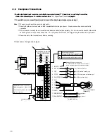
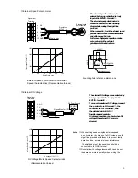
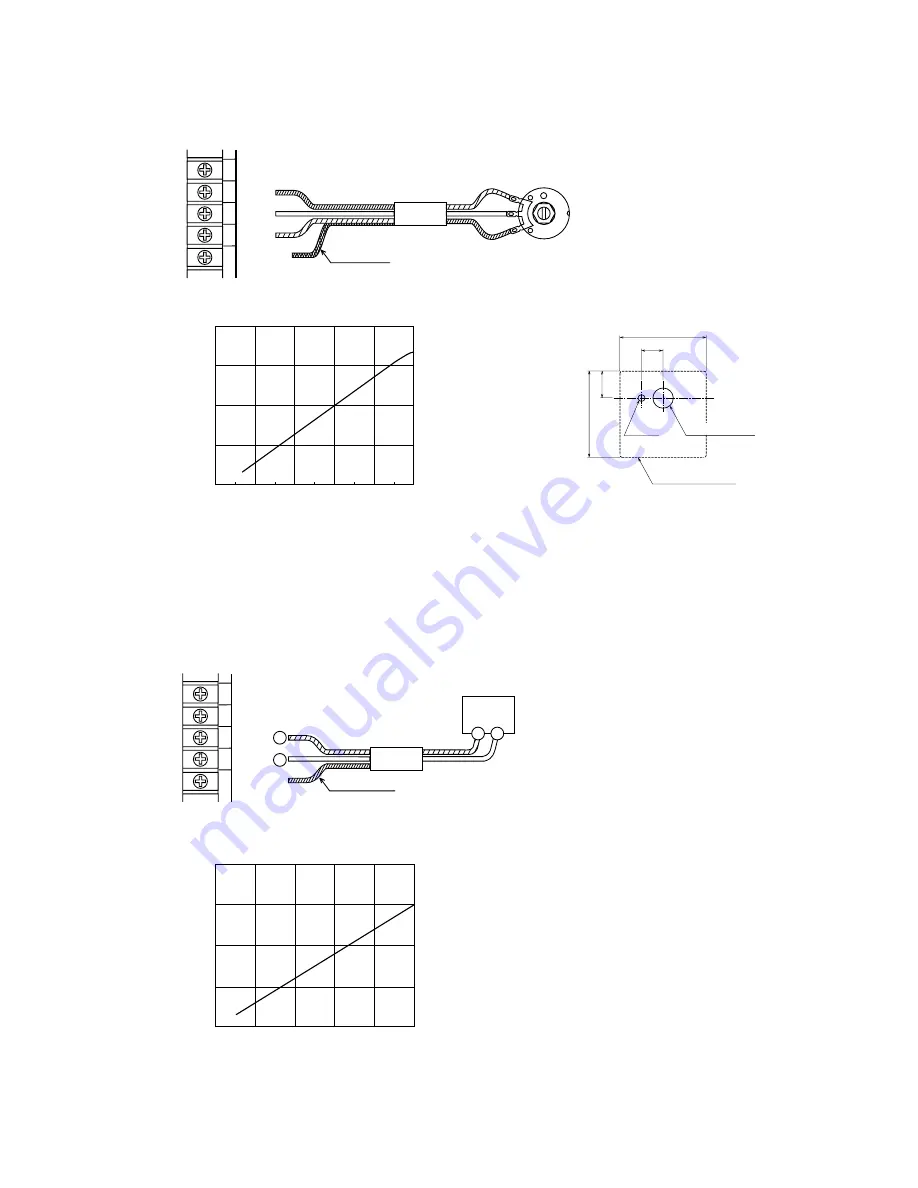
External Speed Potentiometer
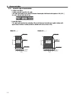
The external potentio meter can be
selected by turning on(switced to low)
input to the EXT.VR. terminal ②.
The external speed potentiometer is
connected as shown in the following
diagram below using the signal line
provided.
When connecting , turn the external speed
potentio meter's knob counterclockwisee
and set the speed 0r/min.
In this case high-speed operation can be
set when turning the external
potentiometer' knob clockwise.
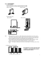
Mounting hole reference dimensions
External Speed Potentiometer Scale/Motor
Speed Characteristics (Representative Values)
13
6
7
8
9
10
3
2
6
7
8
9
10
N.C.
H
M
L
GND
Signal Wire
(
1m
)
External speed
potentiometer
Signal Input
Terminals
1
3
2
Shielded wire
1
3000
2000
4000
1000
0
20
40
60
80
100
Scale Plate Value
Motor speed
〔
r/min
〕
12.5
(.492)
φ3.2
(.126DIA.)
Insulated sheet
40(1.57)
40(1.57)
7.5(.295)
φ
9.5(.374DIA.)
■
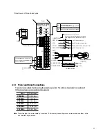
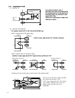
External DC Voltage
The external DC voltage can be selected by
turning on (switchd to low) input to the
EXT.VR. terminal②.
To connect an external DC voltage, connect
the plus wire to the M terminal ⑧, the
minus wire to the L terminal ⑨, and
the shielded wire to GND ⑩.
Insulate unused lead wire.
High speed operation can be set when DC
voltageof the external DC source is
elevated.
Note
・
When setting speed using the external speed
potentiometer or by means of a DC voltage, use the
signal line provided with the unit, to prevent faulty
operation due to external noise or interference.
The shielded wire of the signal line should be
connected to the GND terminal.
・
Do not allow the voltage to exceed 5V, and be sure
there are no errors in polarity when making the
connections.
DC Voltage/Motor Speed Characteristics
(Representative Values)
6
7
8
9
10
6
7
8
9
10
N.C.
H
M
L
GND
Signal Wire(1m)
DC Power Supply
Signal Input
Terminals
Shielded Wire
DC0〜5V
1mAmin.
+
−
+ −
1000
2000
3000
4000
0
1
2
3
4
5
DC Voltage
〔
DCV
〕
Motor Speed
〔
r/min
〕

