


12
•
Always ensure the laser beam is directed at material which does
not have any reflective surfaces. Reflective steel sheet does
not allow for laser use, because it might cause hazardous light
reflection directed at operator, bystanders or animals.
•
Do not replace laser unit with device of other type. All repairs must
be carried out by the manufacturer or authorized person.
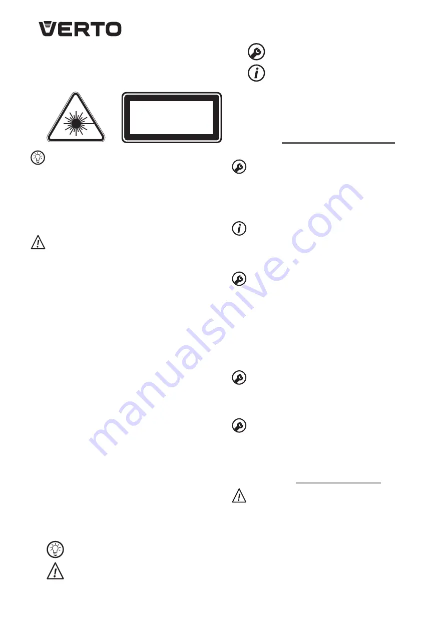
LASER LIGHT, LASER RADIATION
DO NOT LOOK AT THE LASER BEAM
LASER DEVICE CLASS 2
Wavelength: 650 nm; Output: < 1 mW
EN 60825-1:2007
Adjustments other than described in this manual put in danger
of exposition to laser radiation!
CONSTRUCTION AND USE
Mitre saw is designed for cutting wooden pieces that match with the
tool size. Do not use the saw for cutting firewood. Use the mitre saw
accordingly to its purpose only. Attempts to use the mitre saw for
purposes other than specified will be considered an improper use.
Use the mitre saw only with appropriate cutting blades with teeth
with sintered carbide inserts. Mitre saw is designed for light duty
works in workshops and for individual, amateur activities (tinkering).
Use the tool according to the manufacturer’s instructions only!
DESCRIPTION OF DRAWING PAGES
Below enumeration refers to the device elements depicted on the
drawing pages of this manual.
1.
Stationary guard
2.
Bolt for cutting blade fixing
3.
Main handle
4.
Cutting blade shield
5.
Cutting blade
6.
Fence
7.
Table extension
8.
Work table locking knob
9.
Head locking knob
10.
Dust extraction outlet
11.
Cutting blade shield lever
12.
Switch
13.
Transport handle
14.
Carbon brush cover
15.
Head locking pin
17.
Angle scale
18.
Table insert
19.
Work table
20.
Spindle lock button
21.
Work piece locking knob
22.
Vertical pressure locking knob
23.
Laser
24.
Laser switch
25.
Battery compartment
* Differences may appear between the product and drawing
MEANING OF SYMBOLS
CAUTION
WARNING
ASSEMBLY/SETTINGS
INFORMATION
EQUIPMENT AND ACCESSORIE
1. Hex key
- 1 pce
2. Vertical pressure
- 1 pce
3. Slidable table extensions
- 3 pcs
PREPARATION FOR OPERATION
CARRYING THE MITRE SAW
•
Ensure the head is locked in the lowest position when carrying
the mitre saw.
•
Make sure that work table locking knob, head locking knob, and
other safety parts are tightened firmly.
•
When carrying the mitre saw grip the transport handle (
13
). Do
not carry the saw when holding main handle (
3
).
INSTALLATION OF MITRE SAW ON A WORKBENCH
It is recommended to firmly fix the mitre saw to a workbench or a
stand with the use of fixing holes designed for such purpose. They
are located on the mitre saw base (fixing bolts are not included) and
guarantee safe operation and eliminate risk of unwanted machine
shifts during operation.
USING THE SAW ARM (HEAD)
There are two positions of the saw arm, upper and lower. To release
the saw arm from locked lower position, do as follows:
•
Press and hold down the arm.
•
Pull the head locking pin away (
15
) (
fig. B
).
•
Hold the saw arm as it lifts to its upper position.
To lock the saw arm in lower position, do as follows:
•
Press and hold the cutting blade shield lever (
11
) (
fig. C
).
•
Press down the saw arm until it reaches its lower position.
•
Press in the head locking pin (
15
).
INSTALLATION OF TABLE EXTENSIONS
•
Insert ends of table extensions (
9
) into holes located at both sides
of the saw base.
•
Adjust length of table extensions.
•
Fix with the locking knobs (
24
).
VERTICAL PRESSURE
Vertical pressure can be installed in the saw base at either side of the
work table and is fully adjustable to size of the object to be cut. Do
not use the saw without using vertical pressure.
•
Install the vertical pressure in one of the holes in the saw base.
•
Tighten the vertical pressure locking knob (
25
) and work piece
locking knob (
27
).
OPERATION / SETTINGS
Ensure the mitre saw is disconnected from power supply
network before starting any adjustments. To ensure safe, precise
and efficient mitre saw operation, proceed with all adjustment
procedures as a whole.
After finishing all the setting and adjustment procedures ensure
that all keys are collected. Check that all threaded joining
elements are properly tightened.
When making adjustments check that all external parts work
properly and are in good condition. Any worn or damaged part
must be replaced by qualified personnel before starting to use
the mitre saw.
Содержание 52G206
Страница 2: ...2...
Страница 4: ...4 7 22 21 23 10 2 1 3 4 5 6 17 18 19 20 14 13 12 11 15 9 8...
Страница 5: ...5 15 B 4 C 11 press 3 D 13 p r e s s 19 E 5 9 F b a c 9 G d 24 H 25 23 I J 23 d K 2 5 4 20 L 25 24...
Страница 20: ...20 52G206 EN 847 1 RU 2 1 650 0 25 2 650 1 EN 60825 1 2007 1 2 3 4 5 6 7 8 9 10 11...
Страница 21: ...21 12 13 14 15 17 18 19 20 21 22 23 24 25 1 1 2 1 3 3 13 3 15 11 15 7 22 21 12 d 12 9 9 8 00 8 11 E 900 F 5...
Страница 22: ...22 a b F 450 d G 450 15 8 17 19 8 00 450 I 15 9 b c F 9 19 00 17 00 25 24 I H d J 12 11 12...
Страница 26: ...26 11 C 15 7 25 27 12 D 12 9 9 8 0 8 11 E 900 a F 5 b F 450 d G 450 15 8 17 19 8 1 0o 45o I 15 9 b F 9...
Страница 27: ...27 19 00 17 00 19 24 I H d J 12 11 12 15 11 4 5 20 2 K 20 1 4 4...
Страница 61: ...61 52G206 EN 847 1 BG 2 1 W 650 nm 0 25 s 650 nm 1 mW EN 60825 1 2007 1 2 3 4 5 6 7 8...
Страница 62: ...62 9 10 11 12 13 14 15 17 18 19 20 21 22 23 24 25 1 1 2 1 3 3 13 3 15 11 15 7 22 21 12 D 12 9 9 8 00 8 11...
Страница 64: ...64 15 11 4 5 51 2 K 20 1 4 4 1 5 V AAA 25 L 5 mm 14 14...
Страница 75: ...75 15 7 22 21 12 D 12 9 9 8 00 8 11 900 a F 5 a b F 450 d G 450 15 8 17 19 8 00 450 I 15 9 b c F 9 19 00 17 00...
Страница 76: ...76 19 24 I H d J 12 11 12 15 11 4 5 20 2 K 20 1 4 4...
Страница 87: ...87...
Страница 88: ......