Vertiv™ NetSure™ 512
NGBB
-48 VDC Power System User Manual
Proprietary and Confidential © 2022 Vertiv Group Corp.
16
For 24VDC or -58 VDC positions, move the breaker line bus bar one position to the left and reconnect the shorting
bar between the bar you are moving and the one directly to its left. Reconnect the FA alarm strap, and alarm spring jumper
so that the alarm spring directly over the line bus bar you just moved will accept an alarm based on a +24V or -58 VDC
signal from the breaker.
12.
Connect the hardware loosely when making these connections as it will be tightened after the breaker line bus bar is
tightened. Refer to Figure 3.12.
13.
From the front of the unit, attach the breaker line side bus bars to the panel with the screws that you removed previously.
Tighten securely. See Figure 3.9.
14.
Relocate the load side bus bar that is no longer over a line side bus bar to a position that is now over a line side bus bar.
Refer to Figure 3.13.
15.
Remove, flip over, and relocate the voltage indicating label so that the load side bus bars are indicating the correct voltage.
Refer to Figure 3.14.
16.
Re-Install the Lexan cover.
17.
From the rear of the unit tighten the bolts and screws holding the shorting bar, FA alarm strap, and the alarm spring. Refer to
Figure 3.12.
18.
Reconnect all loads keeping in mind that some of the positions have changed voltages.
19.
Ensure that there are no local or remote alarms active on the system.
20.
Close any access panels and the cabinet front door.
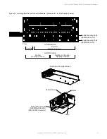
Figure 3.8
Removing the Lexan Cover from the front of the Distribution Panel
Lexan
Cover
Lexan
Cover


