Vertiv™ NetSure™ 512
NGBB
-48 VDC Power System User Manual
Proprietary and Confidential © 2022 Vertiv Group Corp.
15
3.4
Reconfiguring a Dual Voltage Distribution Panel (List DH, DI, DJ, DK, DL,
FG, FH, FI, FJ, FK, FL) in a 582137000 List 27 Distribution Cabinet
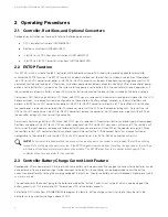
Perform the following procedure to reconfigure a dual voltage distribution panel (List DH, DI, DJ, DK, DL, FG, FH, FI, FJ, FK, FL) in the
top row of a 582137000 List 27 distribution cabinet to move distribution positions from one voltage to another. Blocks of four (4)
positions can be reconfigured from one (1) voltage to another. The panel can be completely converted over to twenty-nine (29) -
48VDC positions if needed with the 564354 kit. See For Re-Configuring to a Single -48V Application (w24V or -58V output)
for this procedure.
DANGER!
Performing this procedure exposes service personnel to battery potential. Exercise extreme caution not to
inadvertently contact or have any tool inadvertently contact any energized electrical termination.
NOTE!
Save all removed hardware. Hardware will be re-used.
WARNING!
Performing this procedure may activate external alarms. If possible, disable these alarms. If these alarms cannot
be easily disabled, notify the appropriate personnel to disregard any future alarms associated with this system while the
procedure is being performed.
DANGER!
All sources of AC and DC power must be completely disconnected from this power system before performing this
procedure. Use a voltmeter to verify no DC voltage is present on the system busbars before proceeding.
DANGER!
Follow local lockout/tagout procedures to ensure DC branch circuit protection devices remain de-energized
during installation at loads, as required.
Procedure
1.
Verify all AC and DC power sources are disconnected from the power system.
2.
Open the cabinet door and rear access panel to cabinet.
3.
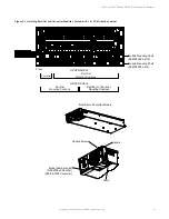
Loosen the screws holding the Lexan cover over the breaker panel. Slightly lift the Lexan cover up and out of the distribution
panel. Refer to Figure 3.8.
4.
Locate the position in the panel where there is a gap between the two voltages.
5.
If there are any breakers present, shut off and remove the bullet breakers from the positions you want to move to the new
voltage.
6.
Label the load leads that are affected.
7.
Disconnect and insulate all affected load leads from the circuit breaker and/or fuse positions.
8.
Disconnect and insulate all affected load return leads from the ground bus bar.
9.
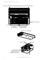
Remove the screws from the breaker line side bus bars from the positions that you will be reconfiguring to the new voltage.
Refer to Figure 3.9.
10.
From the rear of the unit, remove the shorting bar, FA alarm strap, and alarm spring at the point where you would like the
voltage to the right and the left to be different. Refer to Figure 3.10.
11.
For adding -48V positions, move the breaker line bus bar one position to the right and reconnect the shorting bar between
the bar you are moving and the one directly to its right. Refer to Figure 3.11. Reconnect the FA alarm strap and alarm spring
jumper so that the alarm spring directly over the breaker line bus bar you just moved will accept an alarm based on a -48VDC
signal from the breaker.


