


Vertiv™ NetSure™ 512
NGBB
-48 VDC Power System User Manual
Proprietary and Confidential © 2022 Vertiv Group Corp.
34
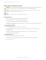
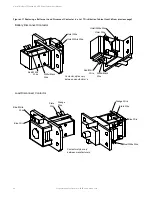
IB2 (Controller Interface Board) and EIB (Controller Extended Interface Board) Replacement in a List 7 or
List 27 Distribution Cabinet
Procedure
NOTE!
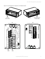
Refer to Figure 4.4 or Figure 4.5 for circuit card locations.
Refer to Figure 4.7 or Figure 4.8 as this procedure is performed.
1.
Performing this procedure may activate external alarms. Do one of the following. If possible, disable these alarms. If these
alarms cannot be easily disabled, notify the appropriate personnel to disregard any future alarms associated with this system
while the procedure is being performed.
DANGER!
Performing the next steps exposes service personnel to battery potential. Exercise extreme caution not to
inadvertently contact or have any tool inadvertently contact any energized electrical termination.
WARNING!
Damage to the circuit card may result if the next step is not followed.
2.
Connect an approved grounding strap to your wrist. Attach the other end to a suitable ground.
3.
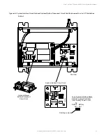
Carefully label the wires connected to the customer connection terminal blocks on the circuit card. These wires must be
connected to the same terminals on the replacement circuit card. Refer to Figure 4.7 or Figure 4.8.
4.
Carefully label the connectors plugged into the circuit card. These connectors must be plugged into the same connectors on
the replacement circuit card. Refer to Figure 4.7 or Figure 4.8.
DANGER!
In the next step, external alarm wiring may be energized from an external source. DO NOT allow bare wire ends to
contact any grounded or energized object.
5.
Remove the external wiring from the customer connection terminal blocks. DO NOT allow the bare wire end to contact any
grounded or energized object. Isolate the wire end with electrical tape. Repeat for each wire to be removed.
6.
Unplug all connectors plugged into the circuit card.
7.
Remove the circuit card from the distribution cabinet.
a)
In a List 7 distribution cabinet, remove the circuit card by removing the screws securing it to the cabinet side wall.
b)
In a List 27 distribution cabinet, remove the circuit card by removing the bracket the circuit card is mounted to from the
cabinet. Remove the circuit card from the bracket.
8.
In this step, ensure you do not intermix the old and replacement circuit cards. Set the switch on the replacement circuit card
to the same setting as the old circuit card. Switch settings are documented in the “SETTING JUMPERS AND SWITCH
OPTIONS” section of the Power System Installation Instructions (IM582137000).
9.
Secure the replacement circuit card to the distribution cabinet.
a)
In a List 7 distribution cabinet, secure the replacement circuit card to the cabinet side wall using the screws removed
above.
b)
In a List 27 distribution cabinet, secure the replacement circuit card to the mounting bracket then secure the mounting
bracket with circuit card to the distribution cabinet.
10.
Plug all connectors removed from the old circuit card into the same position on the replacement circuit card.
DANGER!
In the next step, external alarm wiring may be energized from an external source. DO NOT allow bare wire ends to
contact any grounded or energized object.


