background image

Vertiv™ NetSure™ 512

NGBB

 -48 VDC Power System User Manual 

Proprietary and Confidential © 2022 Vertiv Group Corp. 

18 

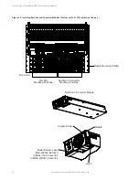
Figure 3.11


Moving the Shorting Bus Bar, Alarm Spring, and FA Alarm Strap 


Figure 3.12


Securing the Shorting Bus Bar, Alarm Spring, and FA Alarm Strap 


Figure 3.13


Relocating Load Side Bus Bar 


Breaker Line

Side Busbar

FA Alarm Strap

Torque: 9.6 in-lbs

Shorting Busbar

Torque: 75 in-lbs

Alarm Spring

Torque: 9.6 in-lbs

Содержание 582137000

Страница 1: ...NetSure 512NGBB 48 VDC Power System User Manual Specification Number 582137000 Model Number 512NGBB ...

Страница 2: ...s not specifically described in this document The products covered by this instruction manual are manufactured and or sold by Vertiv This document is the property of Vertiv and contains confidential and proprietary information owned by Vertiv Any copying use or disclosure of it without the written permission of Vertiv is strictly prohibited Names of companies and products are trademarks or registe...

Страница 3: ...ounting Shelf 7 3 2 1 General 7 3 2 2 System with List 7 Distribution Cabinet 7 3 2 3 System with List 27 Distribution Cabinet 7 3 2 4 Adding a Module to an Existing Module Mounting Shelf 7 3 3 Installing a Field Expansion Module Mounting Shelf in a System with a List 27 Distribution Cabinet 11 3 4 Reconfiguring a Dual Voltage Distribution Panel List DH DI DJ DK DL FG FH FI FJ FK FL in a 582137000...

Страница 4: ...rate injury if not avoided ANSI OSHA This admonition is not used for situations that pose a risk only to equipment data or service even if such use appears to be permitted in some of the applicable standards OSHA ALERT Alerts the reader to an action that must be avoided in order to protect equipment software data or service ISO ALERT Alerts the reader to an action that must be performed in order t...

Страница 5: ...nishments used in this document are listed under Admonishments Used in this Document on page iv Safety and Regulatory Statements Refer to Section 4154 provided with your customer documentation for Safety and Regulatory Statements Déclarations de Sécurité et de Réglementation Reportez vous à la Section 4154 fourni avec les documents de votre client pour les déclarations de sécurité et de réglementa...

Страница 6: ...Vertiv NetSure 512NGBB 48 VDC Power System User Manual Proprietary and Confidential 2022 Vertiv Group Corp vi This page intentionally left blank ...

Страница 7: ... Controller User Manual NCU Controller User Instructions UM1M830BNA USB Drive with All Customer Documentation Power System Installation Instructions IM582137000 Power System Quick Start Guide QS582137000 Power System User Instructions UM582137000 Power System System Application Guide SAG582137000 Module Mounting Shelf Power Data Sheet PD588705300 NCU Controller User Instructions UM1M830BNA Rectifi...

Страница 8: ...unted into an equipment cabinet designed for the power system or as a stand alone system to be mounted in a relay rack This power system is designed to power a load while charging a positive grounded battery This power system is capable of operating in a batteryless installation or off battery for maintenance purposes The power system is designed for operation with the positive output grounded Thi...

Страница 9: ...cess The controller has SNMP V3 capability for remote system management The controller supports software upgrade via its USB port Refer to the NCU Controller Instructions UM1M830BNA for more information Module Mounting Shelf The system contains one 1 to four 4 module mounting shelves depending on system configuration see SAG582137000 which may house rectifier modules optional converter modules and...

Страница 10: ...nverter wait 30 seconds or more until the LEDs on the converter extinguish then re insert the converter For Systems Containing a Battery LVD When the ESTOP signal is removed LVD contactors battery and load type will remain open Rectifiers and optional 48 VDC to 24 VDC converters or optional 48 VDC to 58 VDC converters will remain off The rectifiers will restart when the input power is removed and ...

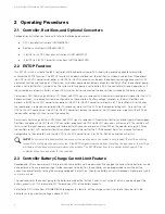
Страница 11: ...a manual battery disconnect switch and indicator Refer to Figure 2 1 Optional Critical Alarm Indicator The system may be equipped with an optional critical alarm indicator which illuminates if the controller issues a critical alarm Refer to Figure 2 2 Figure 2 1 Optional Manual Battery Disconnect Circuit Card List 27 Distribution Cabinet Momentary UP Middle Momentary Down Momentary UP Position Clo...

Страница 12: ...2 Optional Critical Alarm Indicator List 27 Distribution Cabinet 2 4 3 Optional Transient Voltage Surge Suppressor Device TVSS A TVSS device contains an indicator which illuminates when the circuit activates to suppress voltages Refer to Figure 2 3 Figure 2 3 Optional TVSS Device Optional Critical Alarm Indicator Front ...

Страница 13: ...ion Cabinet In the top module mounting shelf rectifier modules can be installed in any mounting position except the far left Converter modules 48 VDC to 24 VDC CANNOT be installed in the top shelf See Figure 3 3 In the bottom module mounting shelf rectifier modules can be installed in any mounting position Converter modules 48 VDC to 24 VDC can be installed in any of the three far right mounting p...

Страница 14: ...mounting position without sliding it in completely See Figure 3 3 or Figure 3 4 for acceptable positions Each module mounting assembly may house rectifier modules optional 48 VDC to 24 VDC converter modules or optional 48 VDC to 58 VDC converter modules depending on configuration 4 Loosen the captive screw on the module s handle Pull the handle down out from the module s front panel this will also...

Страница 15: ...with List 7 Distribution Cabinet Module Mounting Shelf 588705300 List 12 Front Rectifier or Converter Mounting Positions Module Mounting Shelf 588705300 List 2 UPPER SHELF LOWER SHELF Rectifier Mounting Positions Rectifier Mounting Positions Controller Rectifier or Converter Module Model Number Label R48 2000e3 Rectifier C48 24 1500 Converter Captive Screw Latch Handle ...

Страница 16: ...lling Rectifier and Converter Modules System with List 27 Distribution Cabinet Module Mounting Shelf s Rectifier Mounting Positions Rectifier or Converter Mounting Positions Front View Rectifier or Converter Module Model Number Label R48 2000e3 Rectifier C48 24 1500 Converter C48 58 2000P3 Converter Captive Screw Latch Handle ...

Страница 17: ...he expansion module mounting shelf Hardware build up is 12 24 x 3 4 screw and flat washer 1 set per side 12 24 x 3 4 screw and ground washer 1 set per side NOTE Install the ground washers so the teeth make contact with the metal on the mounting angles Torque all screws to 65 in lbs 4 Remove the busbar rear shield from the expansion module mounting shelf NOTE Apply electrical anti oxidizing compoun...

Страница 18: ...fer to the Power System Installation Instructions IM582137000 and install rectifier and converter modules into the expansion module mounting shelf as required 11 For the expansion shelf two sets of converter polarity caution labels are provided loose Based on the converter output voltage apply the correct label to right three converter slots of the expansion shelf 48 VDC OR 24 VDC label P N 600370...

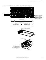
Страница 19: ...ce the mounting angle in position as shown below 2 Remove hardware from the 3 Install the expansion module mounting shelf into the rack 4 Remove busbar rear shield from expansion module mounting shelf 5 Install the busbars provided with the expansion module mounting shelf between the shelves Torque to 60 in lbs 6 Re install the rear busbar shields previously removed Rear Front Rear Busbar Rear Shi...

Страница 20: ...nectors are factory connected These connectors are factory connected Existing Module Mounting Shelf Expansion Module Mounting Shelf Disconnect cable coming from distribution cabinet from this connector on bottom most existing shelf then connect to the same connector on the expansion shelf Now connect these two connectors togethe r Rear View Factory provided jumper to bring connectors to same side ...

Страница 21: ...s present on the system busbars before proceeding DANGER Follow local lockout tagout procedures to ensure DC branch circuit protection devices remain de energized during installation at loads as required Procedure 1 Verify all AC and DC power sources are disconnected from the power system 2 Open the cabinet door and rear access panel to cabinet 3 Loosen the screws holding the Lexan cover over the ...

Страница 22: ... line side bus bars to the panel with the screws that you removed previously Tighten securely See Figure 3 9 14 Relocate the load side bus bar that is no longer over a line side bus bar to a position that is now over a line side bus bar Refer to Figure 3 13 15 Remove flip over and relocate the voltage indicating label so that the load side bus bars are indicating the correct voltage Refer to Figur...

Страница 23: ...y and Confidential 2022 Vertiv Group Corp 17 Figure 3 9 Removing and Securing the Breaker Line Side Bus Bar Figure 3 10 Removing the Shorting Bus Bar Alarm Spring and FA Alarm Strap Screws Torque 15 in lbs Detail A Detail A FA Alarm Strap Shorting Busbar Alarm Spring ...

Страница 24: ...8 Figure 3 11 Moving the Shorting Bus Bar Alarm Spring and FA Alarm Strap Figure 3 12 Securing the Shorting Bus Bar Alarm Spring and FA Alarm Strap Figure 3 13 Relocating Load Side Bus Bar Breaker Line Side Busbar FA Alarm Strap Torque 9 6 in lbs Shorting Busbar Torque 75 in lbs Alarm Spring Torque 9 6 in lbs ...

Страница 25: ...Vertiv NetSure 512NGBB 48 VDC Power System User Manual Proprietary and Confidential 2022 Vertiv Group Corp 19 Figure 3 14 Setting the Correct Polarity ...

Страница 26: ...ceeding DANGER Follow local lockout tagout procedures to ensure DC branch circuit protection devices remain de energized during installation at loads as required NOTE Save all removed hardware Hardware will be re used NOTE This procedure is not applicable when 58VDC distribution panel 582137000GC is installed in row 1 Procedure 1 Verify all AC and DC power sources are disconnected from the power s...

Страница 27: ...NetSure 512NGBB 48 VDC Power System User Manual Proprietary and Confidential 2022 Vertiv Group Corp 21 Figure 3 16 Removing and Sleeving the 24V or 58V FA Cable Lug with Heat Shrink Tube Figure 3 17 Kit 564354 ...

Страница 28: ...p Corp 22 Figure 3 18 Installing Kit 564354 1 4 20 x 5 8 Bolt 1 4 Lock Washer 1 4 Flat Washer Note Apply a thin coating of electrical anti oxidizing compound to the mating surfaces of the busbars Torque the bus bar to the mating area using 75 in lbs Alarm Spring and FA Jumper Screws Torque 9 6 in lbs ...

Страница 29: ... Replacement Information on page 24 and Replacement Procedures on page 25 Troubleshooting Alarm Conditions on the Controller The controller displays alarm conditions as listed in the Available Alarms or Resolving Alarms section of the controller s User Manual Programmable external alarm relays are also available Refer to the System Installation Instructions IM582137000 and the configuration drawin...

Страница 30: ... Fail Alarm after Removing a Rectifier If a rectifier module is removed from the system a rectifier communications failure alarm is generated If the rectifier module will not be replaced the alarm should be cleared Refer to the NCU Instructions UM1M830BNA for a procedure Clearing a Converter Communications Fail Alarm after Removing a Converter If a converter module is removed from the system a con...

Страница 31: ...1M830BNA for a controller replacement procedure 4 6 4 Replacing a Distribution Device General Replace distribution devices with the same type and rating Refer to System Application Guide SAG582137000 for part numbers Distribution Fuse Alarm Fuse Replacement If a distribution fuse opens the associated alarm fuse opens Replace the distribution fuse before replacing the alarm fuse Procedure 1 An alar...

Страница 32: ...use 4 Push the fuse carrier securely back into the mounted fuseholder body Note that a polarizing key on the bottom of the carrier prevents the carrier from being inserted upside down 5 Verify no Fuse Alarms are active Figure 4 2 Replacing a TPS TLS Fuseholder and or Fuse Fuseholder Assembly Longer Side to the Bottom Shorter Side to the Top Fuse Carrier Fuseholder Body TPS TLS Fuse Polarizing Keyw...

Страница 33: ...carrier securely back into the mounted fuseholder body Note that a polarizing key on the bottom of the carrier prevents the carrier from being inserted upside down 5 Verify no Fuse Alarms are active Replacing a Bullet Nose Circuit Breaker Procedure NOTE Refer to Figure 4 3 as this procedure is performed 1 Operate the defective circuit breaker to the OFF position 2 Gently rock the defective circuit...

Страница 34: ...ormed with the system operating Refer to Figure 4 4 or Figure 4 5 for circuit card locations CAUTION When performing any step in these procedures that requires removal or installation of hardware use caution to ensure no hardware is dropped and left inside the shelf otherwise service interruption or equipment damage may occur NOTE When performing any step in these procedures that requires removal ...

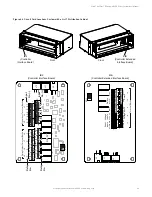
Страница 35: ...3 1 5 2 4 6 3 1 5 2 4 6 3 1 5 2 4 6 3 1 5 2 4 6 3 1 5 Shunt Inputs Voltage Inputs Voltage Inputs Relays Sh1 V1 V2 V3 V5 V7 V8 V4 V6 RLY11 RLY9 Sh2 Sh3 Sh1 Sh2 Sh3 NO C NC NO C NC NO C NC NO C NC NO C NC Relays RLY13 RLY10 RLY12 Terminal Blocks J12 RELAY SW1 7 J2 J11 5 3 1 Relay Output Terminal Blocks Digital Input Terminal Blocks J9 J8 J7 J6 J5 J4 J3 8 6 4 2 8 7 6 5 4 3 2 1 NO C NC NO C NC NO C NC...

Страница 36: ...th a List 27 Distribution Cabinet Optional Manual Battery Disconnect Circuit Card System Interface Circuit Card IB2 Controller Interface Board Front Optional EIB Controller Extended Interface Board Optional EIB Controller Extended Interface Board IB2 Controller Interface Board Optional Manual Battery Disconnect Circuit Card System Interface Circuit Card ...

Страница 37: ...d housing Refer to Figure 4 6 for circuit card location 4 Carefully label the connectors plugged into the circuit card These connectors must be plugged into the same connectors on the replacement circuit card 5 Unplug all connectors plugged into the circuit card 6 Remove the screws securing the circuit card and remove the circuit card from the distribution cabinet 7 In this step ensure you do not ...

Страница 38: ...ergized electrical termination WARNING Damage to the circuit card may result if the next step is not followed 2 Connect an approved grounding strap to your wrist Attach the other end to a suitable ground 3 Remove the top cover from the circuit card housing Refer to Figure 4 6 for circuit card location 4 Unplug all connectors plugged into the circuit card 5 Remove the screws securing the circuit ca...

Страница 39: ...tional Battery Disconnect Circuit Card Replacement in a List 27 Distribution Cabinet Optional Manual Battery Disconnect Circuit Card Top View J1 J2 J3 J4 J5 1 1 555484 0 0 0 X X X X X A X X X X X X X X 1 J4 on System Interface Board Selects to power Controller from Battery Power or not No Battery Pwr Battery Pwr Shorting Jumper System Interface Circuit Card ...

Страница 40: ... wiring may be energized from an external source DO NOT allow bare wire ends to contact any grounded or energized object 5 Remove the external wiring from the customer connection terminal blocks DO NOT allow the bare wire end to contact any grounded or energized object Isolate the wire end with electrical tape Repeat for each wire to be removed 6 Unplug all connectors plugged into the circuit card...

Страница 41: ...o the bare wire end in a previous step DO NOT allow the bare wire end to contact any grounded or energized object After securing the wire gently tug on the wire to ensure that it cannot be pulled out of the terminal block Repeat for each wire to be reconnected 12 Remove the grounding wrist strap 13 Enable the external alarms or notify appropriate personnel that this procedure is finished 14 Ensure...

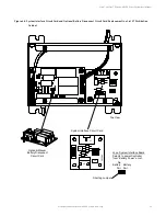
Страница 42: ...er IB2 Temp Probe 1 IB2 Temp Probe 2 J12 RELAY SW1 7 J2 J11 5 3 1 Relay Output Terminal Blocks Digital Input Terminal Blocks J9 J8 J7 J6 J5 J4 J3 8 6 4 2 8 7 6 5 4 3 2 1 NO C NC NO C NC NO C NC NO C NC NO C NC NO C NC NO C NC NO C NC 5 3 1 4 6 2 5 3 1 4 6 2 5 3 1 4 6 2 5 3 1 4 6 2 5 3 1 4 6 2 5 3 1 4 6 2 5 3 1 4 6 2 Switch settings must be in this position to interface with the Controller Relay No...

Страница 43: ...in this position to interface with the Controller J4 SW1 J2 J3 Connector to Controller IB2 Temp Probe 2 IB2 Temp Probe 1 J5 J6 J7 J8 J9 2 4 6 3 1 5 2 4 6 3 1 5 2 4 6 3 1 5 2 4 6 3 1 5 2 4 6 3 1 5 Shunt Inputs Voltage Inputs Voltage Inputs Relays Sh1 V1 V2 V3 V5 V7 V8 V4 V6 RLY11 RLY9 Sh2 Sh3 Sh1 Sh2 Sh3 NO C NC NO C NC NO C NC NO C NC NO C NC Relays RLY13 RLY10 RLY12 Terminal Blocks EIB Assembly 5...

Страница 44: ...bution panel from the distribution cabinet Installing the Distribution Panel NOTE In the following procedure before making busbar to busbar connections apply a thin coating of electrical anti oxidizing compound to the mating surfaces of the busbars 1 Orient the replacement distribution panel into distribution cabinet checking to ensure no wires are pinched Replace the hardware securing the distrib...

Страница 45: ...lation Instructions IM582137000 for a startup procedure 3 Verify no alarms are active Figure 4 9 Replacing a Distribution Panel in a List 7 Distribution Cabinet Battery Disconnect Device Busbar Hardware Alarm Wiring In Line Connector Rear System Load Distribution Device Busbar Hardware Sub System Load Distribution Device Busbar Hardware Distribution Panel Hardware Distribution Panel Hardware Front...

Страница 46: ...e distribution cabinet Installing the Distribution Panel NOTE In the following procedure before making busbar to busbar connections apply a thin coating of electrical anti oxidizing compound to the mating surfaces of the busbars 1 Orient the replacement distribution panel into distribution cabinet checking to ensure no wires are pinched Replace the hardware securing the distribution panel to the d...

Страница 47: ... in a List 27 Distribution Cabinet Distribution Panel Hardware Distribution Panel Hardware Components removed in illustration for clarity only System Load Distribution Busbar Hardware Alarm Wiring Dual Voltage Panel Only Alarm Wiring Rear Front Sub System Load Distribution Busbar Hardware Dual Voltage Panel Only System Load Distribution Busbar Hardware ...

Страница 48: ...tem 2 Remove access panel s as required to access the following connections 3 Disconnect the wiring to the contactor by unplugging the quick disconnects 4 Note the orientation of the contactor to ensure the replacement is installed the same way Unbolt the contactor 4 places and remove Save all hardware Installing the Replacement Contactor 1 Position the replacement contactor oriented the same way ...

Страница 49: ...xt page 5 16 18 x 7 8 Bolt 5 16 Belleville Lock Washer 5 16 Hardened Flat Washer 4 places per contactor Torque to 100 in lbs Apply electrical anti oxidizing compound to busbar mating surfaces Load Disconnect Contactor Battery Disconnect Contactor Rear Load Disconnect Contactor Battery Disconnect Contactor replaced in same fashion as load disconnect contactor Rear Components removed in illustration...

Страница 50: ...abinet cont d from previous page Battery Disconnect Contactor Load Disconnect Contactor Slate Wire Blue Wire Blue White Wire Orange Wire Blue White Wire Blue Wire Slate Wire Orange Wire White Black Wire Violet Wire Violet White Wire Red White Wire Violet White Wire Violet Wire White Black Wire Red White Wire Contactor styles vary between manufacturer s Contactor styles vary between manufacturer s ...

Страница 51: ...27 Distribution Cabinet cont d on next page Load Disconnect Contactor Load Disconnect Contactor 5 16 18 x 1 Bolt 5 16 Belleville Lock Washer 5 16 Hardened Flat Washer 4 places Torque to 100 in lbs Battery Disconnect Contactor Battery Disconnect Contactor Apply electrical anti oxidizing compound to busbar mating surfaces Components removed in illustration for clarity only Rear Rear ...

Страница 52: ...Distribution Cabinet cont d from previous page Load Disconnect Contactor Load Disconnect Contactor 5 16 18 x 1 Bolt 5 16 Belleville Lock Washer 5 16 Hardened Flat Washer 4 places Torque to 100 in lbs Battery Disconnect Contactor Battery Disconnect Contactor Apply electrical anti oxidizing compound to busbar mating surfaces Components removed in illustration for clarity only Rear Rear ...

Страница 53: ...the SPD plug in modules If the color of a status indicator has changed from green to red then that SPD plug in module is damaged 2 Locate and turn OFF the circuit breaker connected to the SPD Assembly being replaced 582137000 List 501 typically located in Row 1 of the power system distribution cabinet 48 VDC bus and in Row 2 of the power system distribution cabinet 58 VDC bus 3 Locate the defectiv...

Страница 54: ...D Assembly Do not remove the wires from the 3 position alarm terminal block 6 Using a small flat blade screwdriver slide the clip securing the defective SPD Assembly to the DIN rail Remove the defective SPD Assembly from the DIN rail 7 Remove the 3 position alarm terminal block half from the replacement SPD Assembly This will not be used and may be saved 8 Orient the replacement SPD Assembly on th...

Страница 55: ...r P N 10034885 Mounting Base and Plug In Modules 582137000501 Power Cable Terminals Recommended Torque 30 in lbs Alarm Contacts Terminals Recommended Torque 2 2 in lbs SPDs Mounted External to Power System Front View 48VDC Return 58VDC Return SPD1 SPD2 SPD3 SPD4 PE PE PE PE SPD Side View Snap Out DC SPD Surge Protection Device Modules 3 Position Alarm Terminal Block ...

Страница 56: ...Vertiv NetSure 512NGBB 48 VDC Power System User Manual Proprietary and Confidential 2022 Vertiv Group Corp 50 This page intentionally left blank ...

Страница 57: ... System User Manual Proprietary and Confidential 2022 Vertiv Group Corp Connect with Vertiv on Social Media https www facebook com vertivI https www instagram com vertiv https www linkedin com company vertiv https www twitter com vertiv ...

Страница 58: ...s or registered trademarks of their respective owners While every precaution has been taken to ensure accuracy and completeness here Vertiv Group Corp assumes no responsibility and disclaims all liability for damages resulting from use of this information or for any errors or omissions Specifications rebates and other promotional offers are subject to change at Vertiv s sole discretion upon notice...

Отзывы: