Page 32
VP-X Installation and Operating Manual
Rev. D (August 5, 2020)
5.9d Backup Alternator (B&C 8 Amp)
The B&C SD-8 8 amp alternator requires a single wire to control the relay
which isolates or connects the SD-8 to the bus. It uses the PMR-1 to
regulate the voltage, which includes a regulator, capacitor, and battery. The
Overvoltage (OV) crowbar module is not needed, as this function is included
in the VP-X. The VP-X does not control the regulator directly, rather it open
and closes a relay which allows the SD-8 output to flow to the bus.
Note that
you can connect the output to the PPS B-Lead post, or alternatively to either
side of the battery contactor.
In a traditional configuration, use the switched
side of the battery contactor (same as the primary alt). In some installations
like an RV-10 where the battery contactor is in the rear of the aircraft, you
can connect the output to the un-switched side of the starter contactor,
located on the firewall (it is electrically identical to the switched side of the
battery contactor, saving you from having to run another wire to the back).
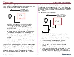
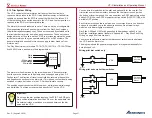
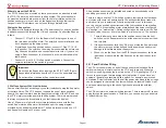
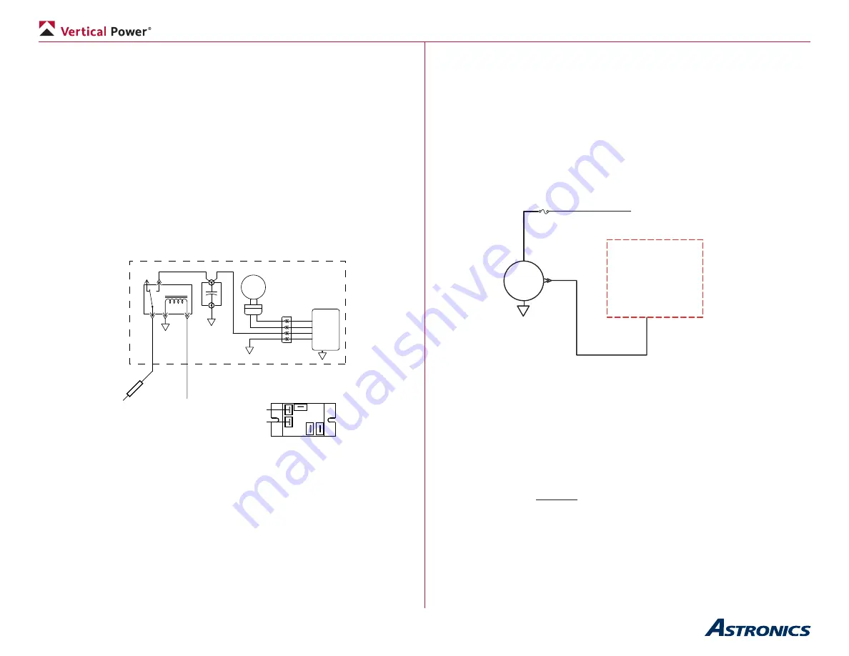
This diagram shows the alternator wiring:
DYNAMO
Regulator V
oltage
14A
WG
B&C SD-8 PM Alternator Package
Wire per B&C instructions
To PPS B-lead post
(no fuse required),
or alternatively,
the switched side
of battery contactor
Fuse
To 2A or
5A circuit
CB set to 2A
Relay Pinout Diagram
R
R
R
R
C
C
NO
NO
NC
NC
20A
WG
• Run a wire from a 2A, 3A or 5A circuit to the coil terminal on the relay
that came with the PMR-1.
•
Set the circuit breaker value to 2A later when configured.
• Connect the other side of the coil terminal on the relay to ground.
• Run a 14 AWG wire from the common terminal on the relay to the
PPS B-lead post, or alternatively through a 10A fuse then to the
either side of the battery contactor. NOTE: locate the fuse near the
contactor (Note: fuse not required with PPS).
5.9e Backup Alternator (Plane Power 30 Amp)
The Plane Power backup alternator requires a single wire for the field. It has
a built-in voltage regulator. The FS1-14 is set to approximately 13.6 volts - a
bit lower than normal as it is meant to be a backup. While the FS1-14 will
work, we recommend using the FS1-14B which is set to run at approximately
14.2 volts, and can be turned on using the backup alternator switch. The
VP-X will not let the primary and backup alternators be on simultaneously.
Please contact Plane Power directly if you’d like further information about
deciding which alternator to use. The VP-X works with either one. This
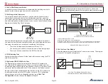
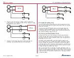
diagram shows the alternator Wiring:
F
B
20A
WG
Backup
ALT
ANL
To PPS B-lead post, or
alternatively, the switched
side of battery contactor
VP-X
To any 5A circuit
Set CB to 5A
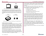
Note: ANL is a type of fuse available in various high-current ratings.
It requires a mounting base and the fuse itself.
Try a web search for “ANL fuse” or go to www.bandc.com
•
Run a 20 AWG wire from any 5A power pin to the field input on
the alternator. This pin will later be configured as the backup (or
secondary) alternator.
•
Set the circuit breaker value to 5A later when configured.
• Run the B-lead wire from the alternator to the PPS B-lead post (no
ANL fuse required), or alternatively to an ANL fuse on the firewall,
then to the switched side of the battery contactor. The switched side
is the large post on the opposite side of the contactor from the large
post connected to the battery. The b-lead is typically a 10 or 12 AWG
wire.
• The alternator failure wire/output on the Plane Power alternator does
not need to be connected. The EFIS will alarm when a low voltage
condition exists, signifying that the alternator is not on or has failed.


