Page 26
VP-X Installation and Operating Manual
Rev. D (August 5, 2020)
5.3 Wiring Harness Construction
Review the Connector Service Manual and Contactor Wiring Guide prior to
proceeding with this section (available at
).
The connectors are labeled with the pin numbers next to each hole on the
black side of the connector.
The wires in the wiring harness kit have a terminal pre-crimped to one end
of each wire intended for use in the power connectors. The terminals for
the power connectors require a special crimp tool. Contact Vertical Power
Support for availability of this crimp tool. The d-sub wires come in longer
lengths that you can trim to the desired length and crimp on the pins with
standard d-sub crimping tool. Do not use generic crimp tools as doing so
may result in a poor mechanical connection.
Construct the wiring harness following these steps:
• Using the Online Planner tool as a guide, and following the
instructions in an earlier section about installing and removing wires,
insert each wire into the correct location in each of the connectors.
•
Double check that the correct wires are in the correct pins in
the correct connector
, based on your planned setup. Remove any
unused wires from the connector. Additional wires can be easily
added later.
• Begin by plugging the connectors into the VP-X and let the wires
hang freely. Group the wires into bundles that go to a specific
location in the aircraft. For example, group all the wires that go out to
the left wing together.
• Run the bundles to their respective general locations. Keep in mind
that ground return wires may also need to share space in the bundle
as well.
• Secure the wires near the VP-X to minimize stress on the wires at
the connector.
5.4
Backbone Wiring
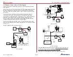
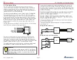
Below is a diagram showing the major parts of the electrical system. Each
section is described in detail in instructions below. Refer to the wiring
instructions from the airframe manufacturer for wire sizing.
Primary
Alt
Backup
Alt
Starter
Contactor
Starter
Battery
Fuse
Battery
Contactor
VP-X
Fuse
(Optional)
Fuse
+
Optional fuse size
should match
alternator output
Backbone wiring diagram.
Note: Backup alternator can be tied to either side of battery contactor.
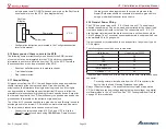
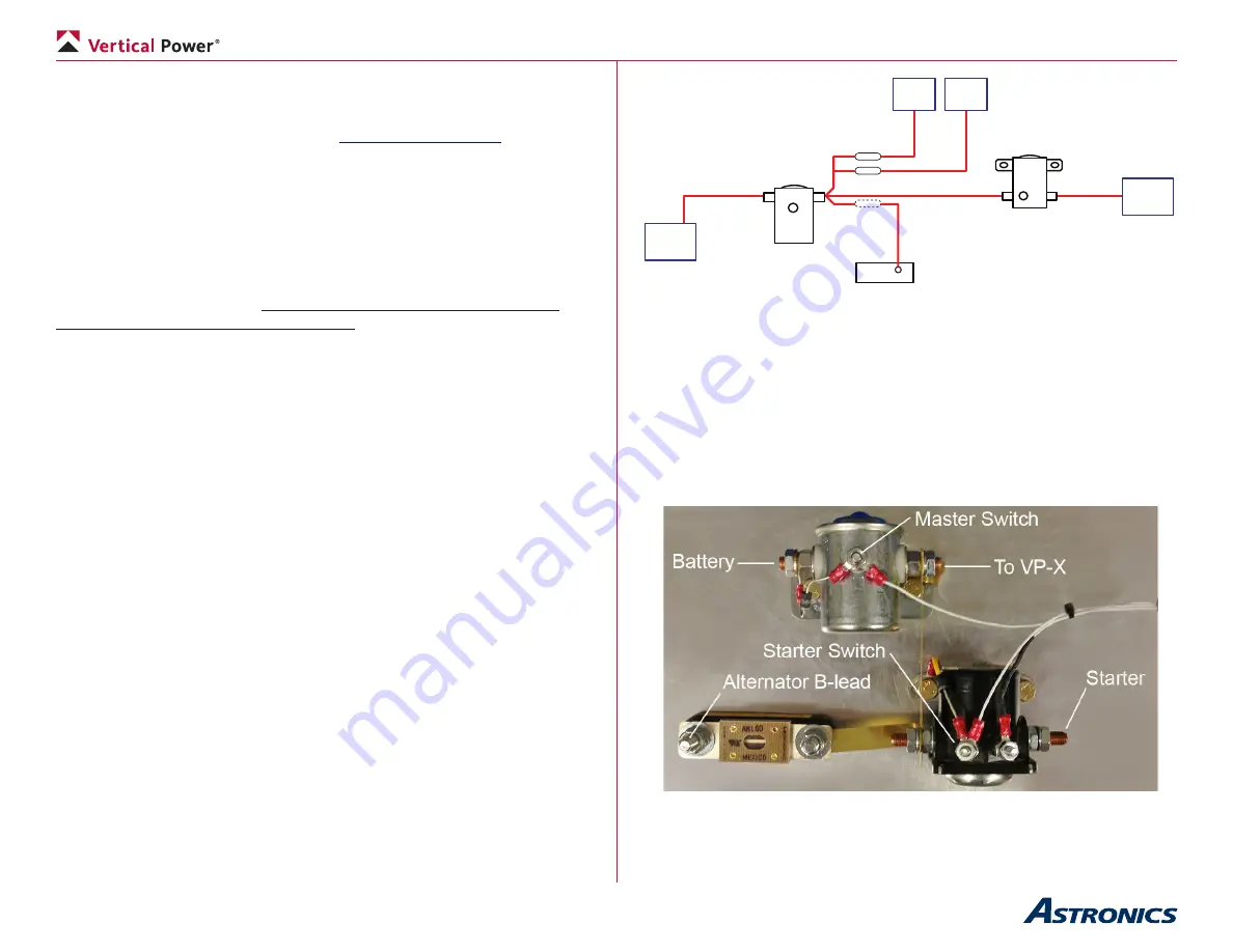
The following information is for the alternative method for primary power. It
adds weight, wiring, and work. We recommend the PPS over the method
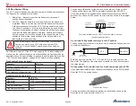
described below. The diagram below shows a typical way to mount the
contactors and fuses. This example is from an RV-7, and your actual
installation may vary. In aircraft with aft-mounted batteries, the master
contactor is located in the back near the battery, and the starter and fuses
are located in the front on the firewall.
Typical contactor and fuse mounting (RV-7 shown)


