Page 18
VP-X Installation and Operating Manual
Rev. D (August 5, 2020)
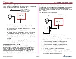
The VP-X
connectors are shown in the diagrams below:
J10
J12
Power Lug
J8
Ethernet
J1 (top)
J2 (bottom)
Shown with mounting brackets installed.
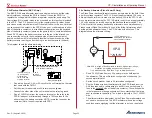
A view of both ends is shown below.
J1
J2
J8
J10
J12
J1 is the top 25 pin d-sub connector and it is male. It mates with a female
connector that contains the wiring harness.
J2 is the bottom 25 pin d-sub connector and it is female. It mates with a male
connector that contains the wiring harness.
4.7
Installing and Removing Power Connector Terminals
The large (black) power connectors allow you to easily install and remove the
wire/terminal assembly.
4.7a Installing terminals
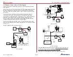
Step 1
: Insert a small screwdriver (max width= 1/8 inch, about 3.0 mm) into
either pry point
Step 2
: Using the housing as a pivot point gently pry out on the white insert,
until it reaches pre-lock position (5.0 mm travel)
Insert screwdriver
Gently pop up white section
Before
After
The white insert should never be removed.
If it is removed, discard the entire connector. Do not attempt to
re-assemble. Contact Vertical Power Support for information
regarding replacement connectors.


