background image

■ 

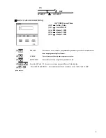
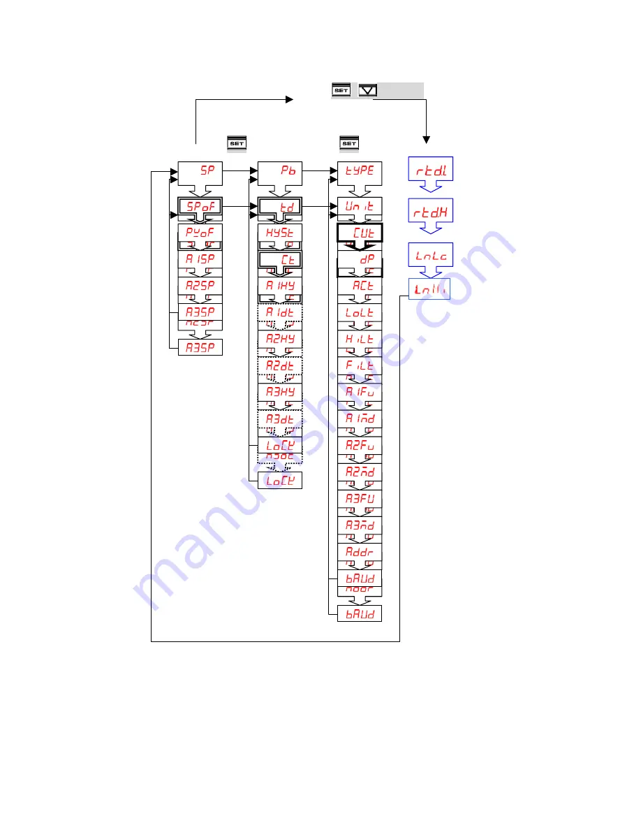
PROGRAMMING LEVEL PARAMETERS 


lst. Prog. Level      2nd. Prog. Level    3rd. Prog. Level   


                                  Press 

+

5 seconds 


Press 

  5 seconds /Press 

  5 seconds                       


6

Содержание VD 26 Series

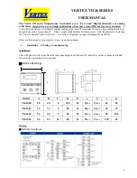
Страница 1: ...the parameters including the Process Variable and Set Point It is fully configurable on input including PT100 RTD There are three simple steps required to get you up and running 1 Installation 2 Wiri...

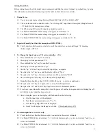
Страница 2: ...play will change and read Type 5 Use the up or down keys to select the input type you require 6 Now press the set key once and the display will read Type 7 Now press the set key a few times until you...

Страница 3: ...ill be charged for repairing it 6 2 All controllers are Relay output as factory standard To have SSR you must especially order them with this option 7 Relay output If you are using a relay output cont...

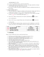
Страница 4: ...w Scale of Linear Input 1999 9999 199 9 999 9 0 0 High Scale of Linear Input 1999 9999 199 9 999 9 100 0 10 Commissioning Having correctly wired the unit you are now ready for the initial turn on 1 Tu...

Страница 5: ...e next programmable parameter press for 5 seconds to move from one programming level to next 2 UP KEY Press to increase the set point or parameter value 3 DOWN KEY Press to decrease the set point or p...

Страница 6: ...PROGRAMMING LEVEL PARAMETERS lst Prog Level 2nd Prog Level 3rd Prog Level Press 5 seconds Press 5 seconds Press 5 seconds 6...

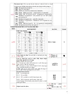
Страница 7: ...ON OFF control mode 0 0 300 0 0 0 Derivative Rate This value is automatically calculated by activating the Auto tune function When 0 0 this parameter will not appear 0 900sec 0 Hysteresis for ON OFF...

Страница 8: ...000 58 1832 B 0 1800 32 3272 R 50 1750 58 3182 S 50 1750 58 3182 N 50 1300 58 2372 C 50 1800 58 3272 D PT 200 850 328 1652 J PT 200 600 328 1112 LINE 1999 9999 Refer to figure K Unit of process value...

Страница 9: ...efer to alarm function section for detail nonE Hi Lo dif H dif L bd Hi bd Lo t on t oFF Alarm 3 mode Refer to alarm mode section for detail nonE Stdy Lath St La HH mm mm SS RS485 address 0 255 0 Commu...

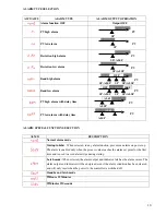
Страница 10: ...CTION SELECTION ALMD DESCRIPTION Normal alarm mode Startup inhibit When selected in any alarm function prevents an alarm on power up The alarm is enabled only when the process value reaches the alarm...

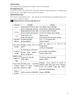
Страница 11: ...ck correct input sensor selection Sensor break error Sensor not connected Replace sensor Check the sensor is connected correctly Keypad no function Keypads are locked Keypads defective Set to a proper...

Отзывы: