control signal input of 3 ~32 Vdc.
8.2 It will not work with SSR’s that have a control signal of 90~250 Vac.
8.3 If you have a SSR that works with 90~250 Vac you will need a relay output controller that will simply
switch the higher voltage signal feeding the Solid State Relay.
8.4 If you have any doubt at all consult your supplier who will assist in checking what exactly you
have or need.
9 Changing the display unit scale
9.1 This section explains how to change the unit display units that correspond to the linear input which as an
example may be 4~20 mA or 0~10 Vdc. It does not change the input signal calibration.
9.2 Press the SET and DOWN keys simultaneously for 5 seconds to access “LnLo” parameter. The display
will show
first. Press the set key twice to get to
9.3 Adjust “LnLo” setting to correspond the low scale and after adjustment press
key once to
access “LnHi” parameter.
9.4 Adjust “LnHi” setting to correspond the high scale and after adjustment press
key once for
normal operation.
9.5 Note: When changing the engineering display units please ensure that the high limit to be found in the
PID level is set to that as well or the display will flash once the high limit in the PID level is exceeded.
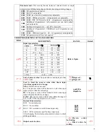
Code
Description
Range
Default
Low Scale of PT100 Not
adjustable
0.0
High Scale of
PT100
Not adjustable
800.0
Low Scale of Linear Input
-1999~9999(-199.9~999.9)
0.0
High Scale of Linear Input
-1999~9999(-199.9~999.9)
100.0
10. Commissioning
Having correctly wired the unit you are now ready for the initial turn on.
1. Turn the power on and watch the display as the controller self tests and powers up.
2. You will be able to see which thermocouple type the unit is set up for.
3. Once the power up is completed you will be looking at the measured temperature.
4. This parameter is identified by the small “PV” light, which will be on.
5. You can now check and set the set point you require.
6. You access this parameter by pressing either the up or down keys once.
7. The “SV” light will now be on and you will be looking at the set value, which you should now set to
about 70% of your final operating temperature.
8. You do this in order to watch the temperature rise to the setpoint at which point the output identified by
light “C1” must turn off.
9. Once the “C1” light is off there should be no power going to the heating elements and the temperature
should stop rising. Should this not happen you must turn off the power and check your wiring.
10. The controller is supplied with a factory default making it an on/off controller. This means that the
temperature will rise up to the setpoint at which point it will switch off (“C1” off) and then drop a little
before the heating turns on again.
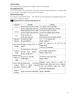
11. The controller is factory set with Pb=0 (on/off control mode). In this mode you can adjust a deadband
around the setpoint by changing the
parameter. It works like this:
4

