Wiring Precautions:
Before wiring please check the model you are using and establish the correct terminals you should use, by using
this information and double checking it against the label on the label on the controller.
1
Mains Power
:
1.1 You can use any mains voltage between 90 and 264 Volts AC (50 or 60 Hz) or DC
1.2 You can also order the controllers with a “Low Voltage DC” input that will accept anything between 18
~ 32 Vac/dc for the mains power voltage.
1.3 The When using DC mains the input is not polarity sensitive
1.4 For Model VD2600 the mains voltage wiring goes on terminals 1 + 2
1.5 For Model VD2601 the mains voltage wiring goes on terminals 13 + 14
1.6 For Model VD2603/2604 the mains voltage wiring goes on terminals 19 + 20
2
Inputs will mostly be either thermocouple or RTD (PT100)
2.1
Firstly check on the box and case label to see if the controller you are installing is T/C meaning
thermocouple or PT100.
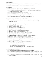
3 To Change the Input type on a VD series controller. (V4)
1. Press and hold the “set” key for 5 seconds.
2. The display will change and read “Pb”
3. Press and hold the “set” key for another 5 seconds.
4. The display will change and read “Type”
5. Use the “up” or “down” keys to select the input type you require.
6. Now press the “set” key once and the display will read “Type”
7. Now press the “set” key a few times until you reach the parameter “HiLt”.
8. Now use the up and down keys to set the input range high limit.
9. Typically these should be either 100, 200, 400, 600 etc etc to suit your application.
10. Now press the “set” key once again to move away from that parameter.
11. Now press the “set” and “down” keys together to revert to the normal position.
12. It is always a good idea after doing this to turn the power off and back on again and watch during the self
test that the correct input has been selected.
13. After turning the power on the display will flash and show the following
a. First the input type will be displayed.
b. Next the measurement units as in ºC or ºF
c. Next the range High limit will be displayed.
d. Lastly it will display the Range Low Limit. (This should always 0ºC)
4
Thermocouples have two wires only.
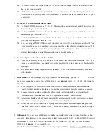
4.1 Points to check are that the thermocouple is connected on the correct terminals.
4.2 For Model VD2600 this is terminals 7 + 8 with the thermove wire on terminal 7 and the –ve
wire is on terminal 8.
2
4.3 For Model VD2601 this is terminals 6 + 7 with the thermove wire on terminal 7 and the –ve
wire is on terminal 6.

