background image

- 16 -

REPLACEMENT PARTS LIST

D

ESCRIPTION

RFS22

RFS32

RFS42

(1)

 Top or Bottom With Magnets

1.

Log Set Complete

10000160

10000160

10000205

1a.

Log Ember Front

KR1

KR1

SR1

1b.

Log Front Left

KR2

KR2

SR2

1c.

Log Front Right

KR3

KR3

SR3

1d.

Log Rear

KR4

KR4

SR4

1e.

Log Top  Left

KR5

KR5

SR5

1f.

Log Top Right

KR6

KR6

SR6

2.

Burner Lava Rock (Package)

57897

57897

57897

3a.

Burner with Tiles Nat.

10000198

10000198

10000866

3b.

Burner with Tiles Prop.

57904

57904

10000867

4.

Ceramic Tile (single)

57803

57803

57803

5a.

Orifice Front Nat.

SEE RATING PLATE FOR ORIFICE SIZE

5b.

Orifice Front  Prop.

SEE RATING PLATE FOR ORIFICE SIZE

6a.

Orifice Main Nat.

SEE RATING PLATE FOR ORIFICE SIZE

6b.

Orifice Main Prop.

SEE RATING PLATE FOR ORIFICE SIZE

7a.

Orifice Pilot SIT Nat.

54273

54273

54273

7b.

Orifice Pilot SIT Prop.

54272

54272

54272

8a.

Orifice Pilot PSE Nat.

10001822

10001822

10001822

8b.

Orifice Pilot PSE Prop.

10001823

10001823

10001823

9a.

Pilot Assembly SIT Nat.

54219

54219

54219

9b.

Pilot Assembly SIT Prop.

54221

54221

54221

10a.

Pilot Asssembly PSE Nat.

10001739

10001739

10001739

10b.

Pilot Assembly PSE Prop.

10001740

10001740

10001740

11.

Pilot SIT

10001295

10001295

10001295

12.

Pilot w/ignitor and cable PSE

10001824

10001824

10001824

13.

Pilot Tubing w/fittings

53211

53211

53211

14.

Manifold Tubing w/fittings

57318

57318

57318

15.

Thermocouple with Interrupter SIT

54912

54912

54912

16.

Thermocouple with Interrupter PSE

10001828

10001828

10001828

17.

Thermopile

53374

53374

53374

18.

Electrode Ignitor w/cable SIT

52465

52465

52465

19.

Ignitor Piezo SIT

52464

52464

50932

20.

Ignitor Piezo Honeywell

2000062

2000062

2000062

21a.

Valve SIT 820 Nat.

52677

52677

52677

21b.

Valve SIT 820 Prop.

52678

52678

52678

22.

Extension Knob Hi/Lo (RN/RP)

10000165

10000165

55162

23.

Extension Knob (On/Off) SIT (RN/RP)

10000166

10000166

55163

24a.

Valve Honeywell Nat.

10001782

10001782

10001782

24b.

Valve Honeywell Prop.

10001759

10001759

10001759

25a.

Valve Eurosit 630 Nat.

51844

51844

51844

25b.

Valve Eurosit 630 Prop.

51845

51845

51845

26.

Fan with Bracket

54103

54103

54103

27.

Electrical Cord (6ft.)

51865

51865

51865

28.

Fan Temperature Sensor

51704

51704

51704

29.

Speed Control

51738

51738

51738

30.

Speed Control Knob

51882

51882

51882

31.

Glass with Gasket -Front

52035

52035

57581

32.

Glass with Gasket - Side

52032

33.

Gasket Glass

57316

57316

57317

34.

Glass Bay Window - Front

57477

35.

Glass Bay Window - Sides

57478

36a.

Frame Window - Left Side

55110

36b.

Frame Window - Right Side

55111

37.

Frame Window - Front

55109

55109

57584

38.

Bay Window Assembly (w/glass)

57582

39.

Trim Frame Window (PB)

53477

52027

57583

(1)

40.

Trim Front Louvre (PB)

53455`

41.

Top Louvre

57263

53977

42.

Front Louvre Assembly

57260

57907

57585

43.

Access Door with Handle

54048

52052

57586

44.

Latch

52057

52057

52057

45.

Remote Switch

53606

53606

53606

46.

Remote Wire Harness with Terminals

57265

57265

57265

47.

Vent Safety Switch

51866

51866

51866

48.

Vent Safety Switch Wiring Harness

54849

54849

54849

49.

Clamp Frame Window

54174

50.

Ceramic Refractory Lining Kit (Not Shown)

10000846

51.

Ceramic Refractory Bay (ONLY Bay Set) (Not Shown)

10000847

Содержание RFS22

Страница 1: ...llow the gas suppliers instructions If you cannot reach your gas supplier call the fire department WARNING IF THE INFORMATION IN THIS MANUAL IS NOT FOLLOWED EXACTLY A FIRE OR EXPLOSION MAY RESULT CAUSING PROPERTY DAMAGE PERSONAL INJURY OR LOSS OF LIFE FOR YOUR SAFETY Installation and service must be performed by a qualified installer Service agency or your gas supplier Free Standing Fireplaces RFS...

Страница 2: ...n 5 Gas Line Installation 5 Installation of Remote Switch for RN RP gas valve 6 Fan Kit 6 General Venting Information 7 Common Flue Installation 7 Retrofitting to an Existing Brick Chimney 8 Vent Safety System 8 Proper Vent Performance 8 Combustion Air 8 Operating Instructions 9 General Glass Information 9 Louvre Removal 9 Trim Removal 9 Glass Removal 9 Glass Cleaning 10 Installation of Logs and B...

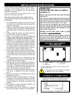
Страница 3: ...ck for clothing nor should Christmas stock ings or decorations be hung in the area of it 9 Undernocircumstancesshouldanysolidfuels wood coal paper or cardboard etc be used in this fire place 10 The flow of combustion and ventilation air must not be obstructed in any way 11 When the fireplace is installed directly on carpeting vinyltileoranycombustiblematerialotherthanwood the fireplace must be ins...

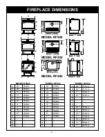
Страница 4: ...29 5 8 752mm J 9 229mm K 5 1 4 133mm L M N MODEL RFS32 A 26 660mm B 26 660mm C 15 1 4 387mm D 19 1 4 488mm E 18 5 8 473mm F 21 533mm G 31 1 2 800mm H 17 3 4 451mm I 29 5 8 752mm J 95 8 244mm K 5 1 4 133mm L M N MODEL RFS22 A 28 1 4 717mm B 28 1 4 717mm C 17 7 8 454mm D 22 3 4 578mm E F G H 22 3 4 578mm I 33 5 8 854mm J 10 5 8 270mm K 5 1 4 133mm L 36 3 8 924mm M 14 3 16 360mm N 17 3 8 441mm MODEL ...

Страница 5: ...ting the gas line The gas line connection can be made with properly tinned 3 8 copper tubing 3 8 rigid pipe or an approved flex connector Since some municipalities have some additional local codes it is always best to consult your local authority and the CAN CGA B149 1 or 2 installation code PREPARATION The use of wall paper adjacent to this fire place is not recommended as the high heat given off...

Страница 6: ...d Fig 7 3 Locate the fan speed control junction box on screw studs provided on base of the fireplace Tighten with 3 8 nuts provided 4 Install thermal sensor element on screw studs located to the right of the gas valve on the burner base 5 Plug in grounded service cord to a convenient wall receptacle THIS FAN ASSEMBLY COMES COMPLETELY WIRED TO ELIMINATE THE NEED FOR ELECTRICIANS THIS ELECTRICAL DEV...

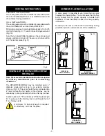
Страница 7: ...ng the full height of the chimney as it is mandatory in most jurisdictions that the chimney be lined Another option is 4 B vent directly off the fireplace Fig 9 11 going up to the chimney liner or up through the roof if no chimney exists VENTING INSTRUCTIONS CANADIAN INSTALLATIONS The venting system must be installed in accordance with the current CAN CGA B149 1 or 2 installation code and the auth...

Страница 8: ...g blown back into room the Vent Safety Switch will automatically shut down the heater 4 Should the heater turn off wait approximately 10 15 minutes to allow for the switch to reset Check draft again If the smoke is not drawn into the draft hood turn the fireplace off and check the cause of lack of draft consult your dealer for expert advice VENT SAFETY SYSTEM This fireplace is equipped with a vent...

Страница 9: ...REMOVAL RFS22 1 Remove frame window brass trim See Trim Removal section 2 Remove remaining bottom 3 8 nut at the bottom of the frame window 3 Remove frame window by pulling it forward and up RFS32 1 Remove frame window brass trim See Trim Removal section 2 Remove remaining bottom 3 8 nut fat the bottom of the frame window 3 Remove 3 8 nut from each side of the frame window Fig 14 4 Remove frame wi...

Страница 10: ...hes Ensure log is secure Top logs must be placed properly into notches RFS42 1 Remove Bay Window assembly and Glass Frame see Glass Frame Removal section 2 Remove logs from packaging 3 Place rear log SR4 on rear bracket Ensure log is seated properly leveled and centered to the unit so it will not move from side to side and it is firmly positioned on the bracket 4 Slip front ember log SR1 down in t...

Страница 11: ...back of the firebox 5 Take left or right side refractory and slide it along the side of the firebox and on top of the bottom support channel Be sure to slide it back to hold the centre piece in place and the leading edge faces forward 6 Fasten top tab support against the refractory to hold it in place 7 Repeat steps 5 and 6 for remaining side refactory 8 Insert refractory pieces into the Bay Windo...

Страница 12: ...ass FrameRemovalinmanual 8 Visiblylocatepilotbythemainburner 9 Turnknobongascontrolcounterclockwise to PILOT C Useonlyyourhandtopushinorturnthegascontrol knob Neverusetools Iftheknobwillnotpushinorturn byhand donottrytorepairit callaqualifiedservice technician Applyingforceoranyattemptedrepairmay resultinafireorexplosion D Donotusethisfireplaceifanyparthasbeenunderwater Immediatelycallaqualifiedse...

Страница 13: ...efective automatic valve Turn valve knob to Pilot Maintain flow to pilot millivolt operator meter should read greater than 10 mV If the reading is okay and the pilot does not stay on replace the gas valve Note An interrupter block not supplied must be used to conduct this test 3 Pilot burning no gas to A Sensing bulb not in proper Make sure sensing bulb is located in bracket on the lower burner Va...

Страница 14: ...ct this test 3 Pilot burning no gas to A Wall switch or wires Check wall switch and wires for proper connections Jumper burner Valve knob ON defective wire across terminals at wall switch if burner comes on Wall Switch ON replace defective wall switch If okay jumper wires across wall switch wires at valve if burner comes on wires are faulty or connections are bad B Thermopile may not be 1 Be sure ...

Страница 15: ... ADJUST PILOT FLAME HEIGHT ALL WIRING CONNECTIONS REPLACE THERMOPILE THERMOCOUPLE NEEDS A MINIMUM OF 14mV DEFECTIVE VALVE TURN TO PILOT METER SHOULD READ GREATER THAN 100 mV IF NOT REPLACE PILOT LIGHTS WITH PIEZO IGNITOR YES YES YES YES PILOT STAYS LIT PILOT LIGHTS MAIN BURNER SYSTEM OK START CHECK VALVE IS TURNED ON ON OFF SWITCH IS NOT TURNED ON WATCH FOR GROUNDED WIRES THERMOPILE NEEDS A MINIMU...

Страница 16: ...17 Thermopile 53374 53374 53374 18 Electrode Ignitor w cable SIT 52465 52465 52465 19 Ignitor Piezo SIT 52464 52464 50932 20 Ignitor Piezo Honeywell 2000062 2000062 2000062 21a Valve SIT 820 Nat 52677 52677 52677 21b Valve SIT 820 Prop 52678 52678 52678 22 Extension Knob Hi Lo RN RP 10000165 10000165 55162 23 Extension Knob On Off SIT RN RP 10000166 10000166 55163 24a Valve Honeywell Nat 10001782 ...

Страница 17: ...2 36 a b 37 39 46 45 39 43 41 42 it H I L O O F F P IL O T 25a b 48 47 40 14 33 38 42 39 34 35 39 43 33 49 26 1 COMPLETE LOG SET RFS22 RFS32 1b 1d 1e 1f 1a 1c 22 23 3a b 4 2 40 8 a b 12 17 16 L O H I PILOT ADJ P I L O T ON OFF 24 a b 20 10 a b 9 a b 1COMPLETELOGSETRFS42 1d 1f 1e 1c 1b 1a ...

Страница 18: ... On Off Button Remote Control MRC2 Temperature Control Remote MRC3 Temperature Control w digital display 24 hour programmable clock IMT Wall Mounted Thermostat REMOTE CONTROL For units with RN RP valves OPTIONS ...

Отзывы: