Veracity Coldstore CSTORE15-3U Скачать руководство пользователя страница 6

VERACITY 

COLDSTORE

  |  

CS

TORE

15-3U

 QUICK START GUIDE  | 

REV 3.0.

3

  |  

Octob

er 201

8

  |  6 

Carefully insert the loaded trays into the COLDSTORE unit, starting from the left (Disk Slot 1) and filling 
each slot in sequence with as many disks as required. The trays should be inserted as follows: 

With the tray level wide open, insert the tray into the slot taking care that the tray guide lines up with the 
disk cage runners.  Slide the tray in fully and then close the lever, engaging the teeth of the lever at the 
bottom with the lip of the disk cage, thus firmly pushing the disk into the slot and into the SATA 
connectors on the backplane. 


Disk insertion should not be forced and should take a medium pressure only.  If the disk will not engage,

check that the tray is correctly aligned – pull the tray out and re-insert.  The tray should run smoothly into the 
slot. 


A cover on the rear of the unit permits access to two, 2.5” solid state disk (SSD) drives. These drives are

fitted as an option for certain COLDSTORE configurations. When SSD drives are fitted, yellow status LEDs 
show constant ON to indicate drive presence and flash when there is a disk fault. A flashing LED also indicates 
it is safe to remove the drive. Seek technical help from your supplier or from Veracity’s technical support team. 


Fitting 2.5” disk drives to the rear drive bays will not provide performance benefits and could the correct

operation of the COLDSTORE. 

I)

Power Up Sequence

Once the disks are properly loaded, switch on the unit using the power switch on the rear panel.

COLDSTORE will boot up and information will be displayed on the front panel LCD.


Once switched on, the unit must NOT be moved, as in common with any disk array type, this may risk

damage to disks in operation.


If setting up more than one COLDSTORE, power on one unit and configure it fully before powering on the

next. Continue this procedure until all COLDSTORES are fully configured.

J) Front Panel Menu

On boot, the front panel LCD will display the following sequence:

Starting up . . . . 
Please wait 

Analysing Disk 1 . . . . 

Analysing Disk 2 . . . . 
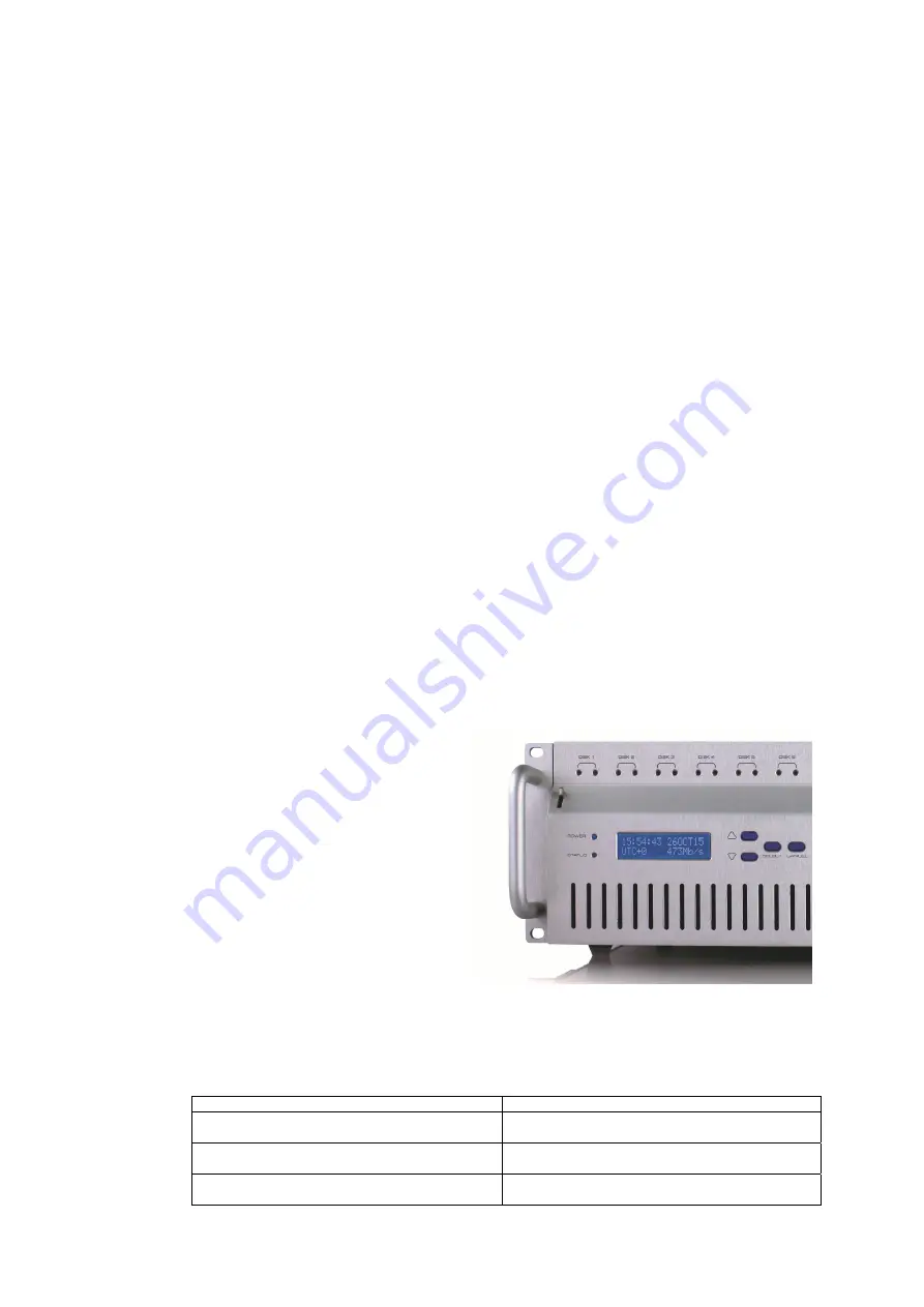
15:54:49  

26OCT15 

UTC+0  

Idle 

COLDSTORE will power up each disk present 
in turn, log the details and capacity, and move 
onto the next disk.  Once all disk checks are 
complete, COLDSTORE will switch to idle 
mode, with time and date display ready for 
input.  

There are four buttons to control the system from the front panel.  These are Up, Down, Select and 
Cancel. 

The default IP address of COLDSTORE is 10.0.0.140 – to check the current IP address setting, carry out 
the following: 

Button Action 

LCD Display Result 

(default display – shows unit date, time and status) 

15:45:54  26OCT15 
IDLE 

Select

SYSTEM STATUS
1-1 Disks

Down \/ 

SETTINGS INFO 
2-1 IP Addresses

Содержание Coldstore CSTORE15-3U

Страница 1: ...Quick Start GUIDE COLDSTORE CSTORE15 3U Version 3 0 3...

Страница 2: ...Overview F Chassis Mounting G System Connections H Disk Loading I Power Up Sequence J Front Panel Menu K COLDSTORE Set up and Maintenance Software SITESCAPE Installing SITESCAPE Getting Connected L Sy...

Страница 3: ...t No 2009 502184 The storage array should NOT be moved once powered up as this is very likely to cause disk damage this applies to all types of disk storage arrays Information in this guide is subject...

Страница 4: ...running Windows 7 or later Windows operating system Ethernet Network including network cables and a switch Preferred Video Management System see website for list of supported systems E System Overview...

Страница 5: ...unit on If network connection redundancy is required a second network cable can be connected between your network switch and the network port labelled ETH2 but before connecting ensure that the COLDS...

Страница 6: ...acity s technical support team Fitting 2 5 disk drives to the rear drive bays will not provide performance benefits and could the correct operation of the COLDSTORE I Power Up Sequence Once the disks...

Страница 7: ...the configuration of your firewall and ensure that the SITESCAPE has full unblocked network access For more information about installing and using SITESCAPE see COLDSTORE User s Guide Installing SITE...

Страница 8: ...have two Ethernet connections labelled ETH1 and ETH2 By default connection ETH1 has IP address 10 0 0 140 subnet mask 255 255 255 0 and gateway 10 0 0 1 This section assumes that the network settings...

Страница 9: ...ORE tab If a warning dialog or other notification is shown by a network firewall protection application choose to allow the SITESCAPE application full access to the network 8 Click the COLDSTORES tab...

Страница 10: ...RE is eventually listed but with status offline and with error Device not found and a manually entered IP address for the COLDSTORE was used then it is possible that SITESCAPE is being prevented from...

Страница 11: ...correct and are writable See COLDSTORE User s Guide gives full details of all operations possible with SITESCAPE Correct time sync may be essential for correct operation depending upon application It...

Страница 12: ...at protocol 7 Click the IPV4 protocol tab The IPV4 Protocol tab for ETH1 connection of the selected COLDSTORE is shown 8 Enter the network settings in IPV4 format as required for your installation Upd...

Страница 13: ...the installation s network switch The SITESCAPE application can then be used to search for and add all the COLDSTORE devices on the installation s network to My Site SITESCAPE can then be used to ful...

Страница 14: ...in the array it may already have been faulty or may have been handled incorrectly during assembly It is essential that all disks are handled carefully are not dropped or even knocked against hard obje...

Отзывы: