4
•
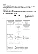
The fan will run in ‘Energy recovery’ speed when the ambient loft temperature is between 18 and 27°C.
•
If the ambient loft temperature exceeds 27°C, the fan will automatically switch to standby (no airflow).
•
The heater (if applicable) will activate when the ambient loft temperature is below the set point (default is
5°C). The set point can be adjusted between 5°C and 20°C. The heater is designed to try and maintain the
heater set point temperature, however will depend on the chosen flow rates and temperature of the incoming
air.
•
Remote Purge/Boost is achievable by using the Boost Switch Link Connector (sold separately –411150).
The unit also incorporates a data logging function. This function will display total runtime of system, time spent in
trickle speed, time spent in energy recovery speed, approximate energy consumption of the fan and approximate
energy consumption of the heater unit. This data is non-resettable
.
B. INSTALLATION
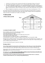
TYPICAL INSTALLATION
Lo-Carbon PoziDry Pro UNIT:
Prior to installation ensure that the loft is adequately ventilated.
Ensure that all water tanks are covered and sealed.
Check that all water pipes are lagged.
Ensure that any extract fans are discharging to the outside and not into the loft.
Check that the loft hatch is tightly sealed.
Ensure that all holes in the ceilings are sealed, i.e. ceiling light fittings etc.
A visual inspection of any flues or chimneys for leakage in the loft should be carried out by the installer.
Flexible ducting is supplied as standard. Ensure that this is pulled out into a smooth single curve to the grille – with
no additional bends or excess ducting. If the application requires a fixed 90 degree bend, straight ducting may be
used. See Spares and Accessories section.
The fan unit can be floor mounted or hung from a roof beam.
Hanging method:
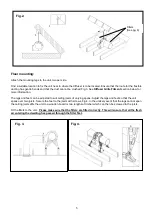
The Lo-Carbon PoziDry Pro can be hung from a roof beam (Fig. 2). Fix the screw eye to a convenient roof beam.
Use the cord provided to loop through the eye and around the handle on the unit, there are various notches for the
cord to run through, tie the two ends together using a suitable knot such as an over hand or fisherman’s knot.
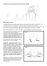
Ensure that the route for the flexible ducting has gentle bends and that the duct cannot be crushed. See
Diffuser
Grille Fitment
section below for more information.
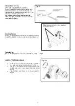
Fit the filters to the unit.
Please make sure that the filters are fitted correctly. This will ensure that all the fresh
air entering the dwelling has passed through the filter first.
Ensure that the screw eye is attached to the beam strongly enough and that the beam is in sufficient
condition to withstand the load. The unit weight is approximately 4 kg.
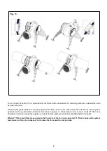
Fig.1.


