Vent-Axia Lo-Carbon PoziDry Pro 476310 Скачать руководство пользователя страница 6


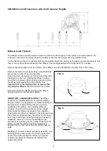
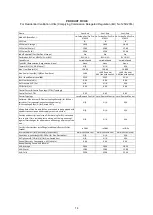
400-600mm Joist Dimensions with Unit Clearance Heights 


Diffuser Grille Fitment: 


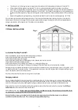
The diffuser must be carefully sited to ensure the maximum effectiveness of the system. It should be fitted in the 
ceiling of a common area, ideally above the landing so that the incoming air can reach all the rooms. 
 
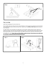
Cut the flexible ducting to a suitable length, where possible stretch the ducting to its maximum extent and ensure that 
there is one continuous smooth bend to the diffuser. The ducting 

must

 remain a minimum of 1m in length. 

 
Remove the loft insulation from the location of the diffuser and cut a 240-260mm diameter hole in the ceiling.  
 
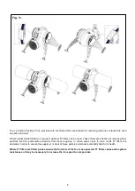
Remove the domed cover panel using a small flat blade 
screw driver to prise it from the assembly. 
Ensure the four locking tabs are folded in and then push 
the spigot in to the hole. Holding the diffuser in place; 
screw the four screws until the locking tabs are holding 
the diffuser tight against the ceiling (Fig.5).

 It is 

important not to over tighten these screws as this 
may warp the diffuser.

 Refit the domed cover panel. 

 
Fit the free end of the flexible ducting to the diffuser 
spigot using the worm drive clip supplied. 


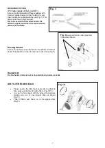
IMPORTANT – SMOKE DETECTORS: 

The diffuser 

should not be situated within 1m of a smoke


detector, 

however if this is not possible the Lo-Carbon PoziDry Pro 
has provisions to blank off the airflow for up to two 
quadrants of the diffuser. Two blanking plates are 
provided; these should be pushed on to the support 
struts inside the diffuser as required. This should be 
done before the diffuser is installed in the ceiling as when 
the screws are tightened down the plates can no longer 
be removed. See Fig.6, showing blocking off opposing 
quadrants, note any 1 or pair of quadrants can be 
blocked off as necessary for the install. These block off 
plates can also be used to ensure the supply air is 
spread across a room rather than directed at close by 
walls.


Blanking off one side reduces the flow by about 6%, but 
blanking off two sides reduces the flow by about 20% 
and so if two sides are blanked off then you should 
consider increasing the fan speed to maintain the 
appropriate airflow.


Fig. 5. 

Fig. 6. 

Содержание Lo-Carbon PoziDry Pro 476310

Страница 1: ...ITH THE ILLUSTRATIONS PLEASE SAVE THESE INSTRUCTIONS Lo Carbon PoziDry Pro Positive Input Ventilation Unit Stock Ref N 476310 PoziDry Pro 476311 PoziDry Pro with Heater 476312 PoziDry Pro FD Installat...

Страница 2: ...2...

Страница 3: ...e Cleaning and user maintenance shall not be made by children without supervision 7 Precautions must be taken to avoid the back flow of gases into the room from the open flue of gas or other fuel burn...

Страница 4: ...at the loft hatch is tightly sealed Ensure that all holes in the ceilings are sealed i e ceiling light fittings etc A visual inspection of any flues or chimneys for leakage in the loft should be carri...

Страница 5: ...e adjusted to suit ceiling joists of varying spans Adjust the legs and feet so that the unit spans over two joists Secure the feet to the joists with screws Fig 4 In the unlikely event that the legs c...

Страница 6: ...er tighten these screws as this may warp the diffuser Refit the domed cover panel Fit the free end of the flexible ducting to the diffuser spigot using the worm drive clip supplied IMPORTANT SMOKE DET...

Страница 7: ...nt Ensure the ducting is securely fixed to the diffuser and fan or heater if applicable via the provided worm drive clips Fig 8 Heater Unit The fan heater unit must not be located directly below a soc...

Страница 8: ...e at removing finer particles such as particulate emissions from diesel engines In urban areas close to main roads F7 filters are advisable in order to ensure the supply air is clear of these particle...

Страница 9: ...arly qualified person in order to avoid a hazard PoziDry Pro PoziDry Pro with Heater unit Ensure the local AC power supply is isolated The product has a pre wired flying lead Connect the brown core to...

Страница 10: ...the connector under the display on the fan 2 Wire the boost switch to the two terminals within the junction box Ensure the cable is secured properly The switch links the two wires together to activat...

Страница 11: ...SIONING Accessing the Commissioning Menu If the fan is powered and the display is not lit then press any button to access the menu After 30 seconds without menu activity the display will switch off an...

Страница 12: ...ton is pressed the display will show At this point enter the three digit code by first pressing or until the first digit is correct then press MODE to move to the next digit Repeat until the code is e...

Страница 13: ...r may be gently cleaned with a vacuum cleaner or washed in a soapy water solution and allowed to air dry before re fitting Do not dry the filter in a tumble dryer When re fitting make sure that the fi...

Страница 14: ...Typology CTRL Typology Control Factor CTRL 0 65 0 65 0 65 Control Typology Local Demand Control Local Demand Control Local Demand Control Declared Max Internal External Leakage Rates for BVUs or carry...

Страница 15: ...15...

Страница 16: ...r warranty if purchased and installed by a recommended contractor against faulty material or workmanship In the event of any part being found to be defective the product will be repaired or at the Com...

Отзывы: