


GB
PANEL/CEILING MOUNTING
1.
For panel/ceiling mounting the fan should be installed into a closed duct system of
at least 1.2m long or protected by an exterior air grille that must comply with the
standard requirements of your country to prevent access to the fans impeller.
2.
Cut a 105mm diameter hole.
3.
Loosen the screw at the bottom of the grille and remove the front grille. Mark the
screw centres through the holes in the fan back plate. Drill, plug and screw into
position.
4.
Attach ducting as required for the installation.
5.
Wire the fan as described in the Wiring section. Adjust any settings as required
(see Setup section).
6.
Replace the grille and tighten the retaining screw.
7.
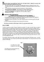
After installation, ensure impeller rotates freely.
WALL MOUNTING
1.
For wall mounting cut a 115mm diameter hole through the wall and insert the wall
sleeve. Slope the sleeve slightly downwards away from the fan. Cut to length and
cement both ends into position flush with the wall faces.
2.
Loosen the screw in the bottom of the grille and remove the front grille. Mark the
screw centres through the holes in the fan back plate. Drill, plug and screw into
position.
3.
Fix exterior grille into position with the louvres positioned downwards. (Note:-The
grille must comply with the standard requirements of your country to prevent access
to the fans impeller).
4.
Wire the fan as described in Section B-Wiring. Adjust any settings as required
(see Section C-Setup).
5.
Replace the grille and tighten the retaining screw.
6.
After installation, ensure impeller rotates freely.
B.
WIRING.
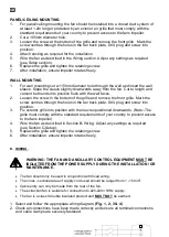
WARNING: THE FAN AND ANCILLARY CONTROL EQUIPMENT MUST BE
ISOLATED FROM THE POWER SUPPLY DURING THE INSTALLATION / OR
MAINTENANCE.
•
The fan should only be used in conjunction with fixed wiring.
•
The cross - sectional area of supply cord used should be ranged from 1 -1.5mm
2
.
•
Cable entry can only be made from the rear of the fan.
•
The extraction fan is suitable for connection to 220-240V 50Hz supply.
•
The fan is a class II double insulated product and
MUST NOT
be earthed.
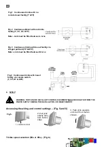
1. Select and follow the appropriate wiring diagram.
(Fig. 1, 2, 3 & 4)
2. Check all connections have been made correctly and ensure all terminal connections
and cable clamps are securely fastened.
Ls
Содержание 8000000009
Страница 22: ......
Страница 23: ......
Страница 24: ...www vent axia be www vent axia nl www vent axia de 473176A 0616...