Vent-Axia 8000000009 Скачать руководство пользователя страница 2

GB 


IMPORTANT:READ THESE INSTRUCTIONS BEFORE COMMENCING THE 

INSTALLATION 

DO NOT install this product in areas where the following may be present or occur: 

  Excessive oil or a grease laden atmosphere. 

  Corrosive or flammable gases, liquids or vapours. 

• 

Ambient temperatures higher than 40°C or less than –5°C. 

• 

Possible obstructions which would hinder the access or removal of the Fan. 


SAFETY AND GUIDANCE NOTES 

A. 

All wiring to be in accordance with the current I.E.E. Regulations, or the 
appropriate standards of your country and 

MUST 

be installed by a suitably 

qualified person. 

B. 

The Fan should be provided with a local isolator switch capable of 
disconnecting all poles, having a contact separation of at least 3mm.  

C. 

Ensure that the mains supply (Voltage, Frequency, & Phase) complies with the 
rating label. 

D. 

The Fan should only be used in conjunction with the appropriate products. 

E. 

The fan should only be used in conjunction with fixed wiring. 

F. 

When the Fan is used to remove air from a room containing a fuel-burning 
appliance, ensure that the air replacement is adequate for both the fan and the 
fuel-burning appliance. 

G. 

 The Fan should not be used where it is liable to be subject to direct water spray 

for prolonged periods of time. 

H. 

Where ducted Fans are used to handle moisture-laden air, a condensation trap 
should be fitted in any vertical exhaust ducts.  Horizontal ducts should be 
arranged to slope slightly downwards away from the Fan. Ducts passing 
through cold voids must be suitably insulated. 

I. 

 This appliance is not intended for use by persons (including children) with 

reduced physical, sensory or mental capabilities, or lack of experience and 
knowledge, unless they have been given supervision or instruction concerning 
use of the appliance by a person responsible for their safety. 

J. 

Young children should be supervised to ensure that they do not play with the 
appliance. 


This product should not be disposed of with household waste.  Please recycle where facilities exist.  Check 
with your local authority for recycling advice. 


DESCRIPTION


The Sylph 100mm fan is a continuously running extract fan for kitchens, utility rooms, 
bathrooms and toilets. The fan can be wall or panel/ceiling mounted. 
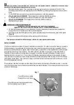
A.  INSTALLATION


IMPORTANT:

 The fan should only be used in conjunction with fixed wiring. 

Siting 
the 
fan. 


Содержание 8000000009

Страница 1: ...llation et de c blage FR Installations und Verdrahtungsanweisungen DE Montage en bekabelingsinstructies NL PLEASE READ INSTRUCTIONS IN CONJUNCTION WITH ILLUSTRATIONS PLEASE SAVE THESE INSTRUCTIONS VEU...

Страница 2: ...ment is adequate for both the fan and the fuel burning appliance G The Fan should not be used where it is liable to be subject to direct water spray for prolonged periods of time H Where ducted Fans a...

Страница 3: ...om of the grille and remove the front grille Mark the screw centres through the holes in the fan back plate Drill plug and screw into position 3 Fix exterior grille into position with the louvres posi...

Страница 4: ...ickle with boost facility via remote switch T TP HT HTP Fig 1 Continuous trickle with no remote boost facility T TP 2 Pull grille slightly away from bottom edge 3 Push grille upwards until clear from...

Страница 5: ...r JP2 in place there will be no overrun timer when the LS connection is switched off the fan will leave boost Pullcord TP HTP The integral pullcord activates the timer The fan will boost for 15 JP2 of...

Страница 6: ...loth until clean The fan has sealed for life bearings which do not require lubrication DATA LOGGER The fan records the number of days it has been running for In order to use this feature power to the...

Страница 7: ...teur et pour l appareil concern G Le ventilateur ne doit pas tre utilis dans un endroit o il risque d tre expos directement et longtemps des pulv risations d eau H Dans le cas de ventilateurs car n s...

Страница 8: ...de niveau avec les parois du mur 2 D vissez la vis situ e au bas de la grille et d posez la grille frontale Marquez les centres des vis travers les trous de la contre plaque du ventilateur Percez ins...

Страница 9: ...bit constant continu sans d clenchement de marche forc e distance T et TP 2 cartez l g rement la grille du bord inf rieur 3 Poussez la grille vers le haut jusqu ce qu elle puisse tre s par e du ch ssi...

Страница 10: ...en marche forc e pendant 15 minutes apr s la coupure de la phase commut e LS Si le cavalier JP2 est en place la temporisation de d passement est occult e teindre la phase commut e LS provoque l arr t...

Страница 11: ...a ade du ventilateur l aide d un chiffon humide Le ventilateur est muni de paliers herm tiques roulements graiss s vie qui ne n cessitent aucune lubrification ENREGISTREUR DE DONN ES L enregistreur de...

Страница 12: ...taustausch f r den L fter und die Kraftstoffverbrauchseinheit sichergestellt werden G Der L fter sollte nicht an Orten eingesetzt werden an denen er m glicherweise f r l ngere Zeit einem direkten Wass...

Страница 13: ...sen Sie die Schraube unten im Gitter und entfernen Sie das Frontgitter Markieren Sie die Befestigungsl cher durch die L cher der L fterr ckplatte an der Wand Bohren und d beln Sie die Wand und montier...

Страница 14: ...ernt ist 1 L sen Sie die Schraube Abb 5 Abb 2 Konstanter Boost ohne Leerlauf Funktion T TP HT HTP Hinweis Es muss eine Verbindung zwischen L und Ls installiert werden Abb 3 Konstante Leerlauf Funktion...

Страница 15: ...rt wenn der LS Anschluss deaktiviert wird Wenn der Jumper JP2 aktiviert ist ist kein Nachlauftimer vorhanden bei Deaktivierung des LS Anschlusses verl sst der L fter den Boostmodus Zugtaster TP HTP De...

Страница 16: ...erseite mit einem feuchten Tuch bis Unreinheiten beseitigt sind Der L fter verf gt ber versiegelte wartungsfreie Lager die nicht geschmiert werden m ssen DATENLOGGER Der L fter zeichnet die Anzahl der...

Страница 17: ...is voor zowel de ventilator als het op brandstof werkende apparaat G De ventilator mag niet worden gebruikt in ruimten waar hij voor langere perioden bloot kan staan aan directe waternevel H Wanneer...

Страница 18: ...juiste positie vast 2 Draai de schroef in de onderkant van het rooster los en het rooster aan de voorzijde verwijderen Markeer de schroefgaten via de gaten in de achterplaat van de ventilator Boren p...

Страница 19: ...e onderste rand 3 Druk het rooster naar boven tot het chassis van de ventilator vrij ligt 1 Schroef losdraaien Fig 5 Fig 2 Continuboost zonder vertragingsmogelijkheid T TP HT HTP Opmerking Verbinding...

Страница 20: ...eschakeld Wanneer jumper JP2 aanwezig is werkt de uitlooptimer niet als de LS verbinding wordt uitgeschakeld verlaat de ventilator de boostmodus Trekkoord TP HTP Het ge ntegreerde trekkoord activeert...

Страница 21: ...met een vochtige doek schoon De ventilator heeft gesealde voor levensduur gesmeerde lagers deze hoeven dus niet te worden gesmeerd DATALOGGER De ventilator registreert het totale aantal dagen dat de v...

Страница 22: ......

Страница 23: ......

Страница 24: ...www vent axia be www vent axia nl www vent axia de 473176A 0616...

Отзывы: