background image

E

RASE

 L

INK

 P

ROCESS

1.A

CTIVATE THE

L

INK MODE OF THE RANGE HOOD

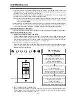
Push and hold button 

E

for 3 seconds. After the 3-second hold, button 

E

backlight blinks 

3 times quickly (low to high intensity) and then all 4 speed levels backlights start to oscillate
between mid and low.

2.E

RASE ALL LINKED

L

INK

L

OGIC DEVICES

Push and hold button 

B

for 3 seconds to start the “Erase-link” process, all 4 speed levels

backlights flash in rotation until links are erased (not visible when small number of linked
devices).

3.E

XIT THE

L

INK MODE OF THE RANGE HOOD

Press and hold button 

E

for 3 seconds. After the 3-second hold, button 

E

backlight blinks 

3 times quickly (low to high intensity) and it exits the 

Link mode. Link mode remains activated

for 4 minutes if no other operation is done.

14.OPERATION (

CONT

D

)

15.WARRANTY

VENMAR VENTILATION FIVE-YEAR WARRANTY

Venmar Ventilation Inc. warrants to the original consumer purchaser of the Venmar Connaisseur
CIS700 Series range hood that such product will be free from defects in materials or workmanship for
a period of five (5) years from date of original purchase. This warranty includes in-home service for the
first year and workshop service for the four (4) remaining years.
THERE ARE NO OTHER WARRANTIES, EXPRESS OR IMPLIED, INCLUDING, BUT NOT LIMITED
TO, IMPLIED WARRANTIES OF MERCHANTABILITY OR FITNESS FOR A PARTICULAR PURPOSE.
VENMAR VENTILATION INC. WILL NOT BE HELD RESPONSIBLE FOR ANY CLAIMS OVER THE
ORIGINAL PURCHASE PRICE OF A VENMAR CONNAISSEUR CIS700 SERIES RANGE HOOD
NOR HELD RESPONSIBLE FOR SUBSEQUENT DAMAGE OR INCIDENT.
During the period stated above, Venmar Ventilation Inc. will, at its option, repair or replace without
charge any product or part which is found to be defective under normal use and service. THIS 
WARRANTY DOES NOT EXTEND TO ANY LIGHT BULBS AND FILTERS.
This warranty does not cover a) normal maintenance and service b) any products or parts which have
been subject to misuse, negligence, accident, improper maintenance or repairs made by other than
Venmar Ventilation Inc., or c) a faulty installation or installation contrary to recommended installation
instructions.
Warranty service is to be completed by an authorized Service Center designated by Venmar Ventilation
Inc. Where applicable, in-home service will be made available only in areas where a contracted 
service provider offers service. If in-home service is not available, the product will be repaired or
replaced, at Venmar’s discretion, by the nearest authorized service provider. The unit removal and 
reinstallation works are under the customer responsibility, and Venmar cannot be charged for them.
The duration of any implied warranty is limited to the 5-year period as specified for the express 
warranty. Some provinces do not allow limitation on how long an implied warranty lasts, so the above
limitation may not apply to you.
VENMAR VENTILATION INC'S OBLIGATION TO REPAIR OR REPLACE AT VENMAR 
VENTILATION INC'S OPTION, SHALL BE THE PURCHASER'S SOLE AND EXCLUSIVE 
REMEDY UNDER THIS WARRANTY. VENMAR VENTILATION INC SHALL NOT BE LIABLE FOR
INCIDENTAL, CONSEQUENTIAL OR SPECIAL DAMAGES ARISING OUT OF OR IN CONNECTION
WITH PRODUCT USE OR PERFORMANCE. SOME PROVINCES DO NOT ALLOW THE 
EXCLUSION OR LIMITATION OF INCIDENTAL OR CONSEQUENTIAL DAMAGES, SO THE ABOVE
LIMITATION OR EXCLUSION MAY NOT APPLY TO YOU.
This warranty gives you specific legal rights and you may also have other rights, which vary from
province to another. This warranty supersedes all prior warranties.
To contact Venmar Ventilation Inc. warranty service call 1-800-567-3855 in Canada. In order to qualify
for a warranty claim, the owner of a Venmar Connaisseur CIS700 Series range hood must have the
model and serial number along with a proof of the original purchase date. At the time of requesting
service, describe the nature of any defect in the product or part.

Venmar Ventilation Inc., 550 Lemire Blvd., Drummondville, QC  J2C 7W9   (1-800-567-3855)

www.venmar.ca    www.ispira.ca

- 18 -

Содержание CIS700 SERIES

Страница 1: ...R HOMEOWNER USE AND CARE INFORMATION ON PAGES 14 TO 18 Venmar Ventilation Inc 550 Lemire Blvd Drummondville QC J2C 7W9 1 800 567 3855 REGISTER YOUR PRODUCT ON LINE AT www bnv ca For additional information visit www venmar ca or www ispira ca HB0117 INSTALLATION INSTRUCTIONS READ AND SAVE THESE INSTRUCTIONS ...

Страница 2: ... or medium settings b Always turn hood ON when cooking at high heat or when flambeing food i e Crêpes Suzette Cherries Jubilee Peppercorn Beef Flambé c Clean ventilating fans frequently Grease should not be allowed to accumulate on fans filters or exhaust ducts d Use proper pan size Always use cookware appropriate for the size of the surface element WARNING TO REDUCETHE RISK OF INJURYTO PERSONS IN...

Страница 3: ...zed ductwork elbows and roof cap Connect metal ductwork to cap and work back towards the hood location Use 2 metal foil duct tape to seal the joints Run 3 wire power supply cable to installation location We recommend to install the hood at a minimum distance of 30 above cooking surface A maximum of 36 above cooktop is highly recommended for best capture of cooking impurities 1 INSTALL DUCTWORK 3 8...

Страница 4: ...ate box Installation manual Bag of parts taped on the blower box including 2 wire connectors 1 wire clamp 8 no 10 x 1 wood screws 8 washers 2 no 8 x 1 2 quadrex screws 10 no 8 x 3 8 quadrex screws 17 no 10 32 locknuts 50 no 10 32 x 1 2 quadrex screws Parts sold separately Ducts elbows wall and roof caps Optional flue extension for 10 ft ceilings model no 19324 LinkLogic remote control model no ACW...

Страница 5: ...port the total weight of the hood and should not be larger than 9 x 9 10 10 93 8 93 8 103 8 103 8 HK0062A MAX 9 FRAMING INNER EDGE When building framework always follow all applicable construction codes and standards WARNING 2 Finish ceiling surface Be sure to mark the location of the ceiling joists and cross framing Bring house wiring through finished ceiling HD0432 CEILING JOISTS CROSS FRAMING H...

Страница 6: ...s Position the mounting plate in such a way that one of the sides without a T will be facing the front of the hood Secure mounting bracket to the ceiling using 8 no 10 x 1 wood screws 2 on each corner Make sure screws are driven into the center of the framing for maximum strength HD0442 CEILING MOUNTING BRACKET 8 ROUND DUCTWORK FRONT OF THE HOOD 6 4 INSTALL MOUNTING BRACKET CONT D 5 ASSEMBLE ANGLE...

Страница 7: ...lue part no 19324 sold separately 4 additional angle brackets and additional mounting hardware are included with the optional extension flue If need be assemble a third set of 4 angle brackets to the second angle bracket set according to the length needed Use 16 no 10 32 x 1 2 quadrex screws and 16 no 10 32 lock nuts 4 at each angle bracket connection 7 5 ASSEMBLE ANGLE BRACKETS CONT D HD0422 FOR ...

Страница 8: ...nel with the control pictogram on the front of the hood 4 While holding glass panel pre tighten previously removed nuts by hand Ensure glass panel is centered Then using a 3 8 socket tighten nuts completely 5 Repeat the same steps for the second glass panel installation 6 Reinstall electrical compartment cover 7 INSTALL GLASS PANELS WG MODEL ONLY The WG hood model decorative glass panels are sold ...

Страница 9: ...located on top right hand corner of blower box 1 to ease wire clamp installation included Install wire clamp and push flap back in place Secure flap to blower box 2 using 1 no 8 x 3 8 quadrex screw NOTE Install wire clamp diagonally as illustrated at right as its screws will be easier to tighten when the blower box will be attached to the angle brackets 9 8 PREPARE HOOD ALL MODELS HO0188 1 2 HE012...

Страница 10: ...luded Remove tape on damper HJ0066 10 8 PREPARE HOOD ALL MODELS CONT D 5 Measure the required length of 8 round metal duct from the adapter damper to the ductwork rough in in the ceiling Connect this section of duct to the adapter damper and seal joint with metal foil duct tape HJ0067 ...

Страница 11: ...et 9 INSTALL HOOD BE CAREFUL when installing the decorative flue and hood they may have sharp edges WARNING 11 1 Attach blower box assembly to lower angle brackets using 16 no 10 32 x 1 2 quadrex screws 4 per angle brackets Connect hood duct to ceiling duct and seal joint with metal foil duct tape NOTE Ensure electrical channel is face to where the front of the hood will be positioned 2 Run house ...

Страница 12: ... 4 out of 8 screws illustrated at right 5 Slide the lower flue down on top of the hood and secure from inside the hood using 4 no 8 x 3 8 quadrex screws included 6 Remove protective plastic film from hood and flues 9 INSTALL HOOD CONT D 12 HD0426 HD0427 SCREW LOCATIONS SCREW LOCATIONS ...

Страница 13: ...ound screw DO NOT FORGET TO CONNECT THE GROUND Reinstall electrical box cover ensuring its 3 tabs are tucked inside the electrical channel HE0120 GROUND SCREW 2 Connect blower HE0121 11 REINSTALL BAFFLE FILTERS CAUTION Remove protective plastic film covering filters before reinstalling them HO0180 2 Rest rear filters edge on filter springs in the range hood Using knob tilt up the filters into posi...

Страница 14: ... CARE BAFFLE FILTERS Baffle filters should be cleaned monthly Remove baffle filters by pushing them towards the back of hood and rotating downward Use a warm detergent solution to clean the filters Let them dry and reinstall them Baffle filters are dishwasher safe Clean all metal filters in the dishwasher using a non phosphate detergent Discoloration of the filter may occur if using phosphate dete...

Страница 15: ...laster dust or any other construction residues reach the hood During construction renovation cover the hood to make sure no dust sticks to stainless steel surface STAINLESS STEEL GLASS PANELS Hot water with mild soap or glass cleaner is all that is usually needed When using mild soap rinse with clear water Wipe dry with a clean soft cloth to avoid water marks 14 OPERATION Always turn your blower o...

Страница 16: ...high intensity and flash 3 times it will then fade out to its low intensity to indicate that the control interface is unlocked B E SPEED SELECTION BUTTONS Press the button corresponding to the desired blower speed from 1 for low speed to 4 for high speed The chosen speed button will light to its high intensity then fade to its mid intensity To turn off the blower press once more on the correspondi...

Страница 17: ...or until beep is heard When the tab is released the remote control confirms initialization by turning ON the backlight of the Room Light ON and Off button Press the Room Light OFF button to stop the flashing Initialization of the remote control is now completed 2 ACTIVATE THE LINK MODE OF THE RANGE HOOD Push and hold button E for 3 seconds After the 3 second hold button E backlight blinks 3 times ...

Страница 18: ...products or parts which have been subject to misuse negligence accident improper maintenance or repairs made by other than Venmar Ventilation Inc or c a faulty installation or installation contrary to recommended installation instructions Warranty service is to be completed by an authorized Service Center designated by Venmar Ventilation Inc Where applicable in home service will be made available ...

Страница 19: ...WHT ORG BLK YEL BLK WHT WHT L AMP L AMP L AMP L AMP HE0119A 120 VAC L INE N EUTRAL G ROUND F AN MOTOR BLU WHT ORG BLK GRY BRN WHT 25 µF 4 3 2 1 3 2 1 3 2 1 COLOR CODE BLK BLU BRN GRY ORG BLACK BLUE BROWN GREY ORANGE RED WHT YEL RED WHITE YELLOW RED BLK BLK BLK YEL YEL YEL WHT WHT WHT WHT 16 WIRING DIAGRAM 19 ...

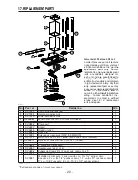
Страница 20: ... 1 SV19232 CEILING MOUNTING BRACKET 1 2 SV19231 UPPER DECORATIVE FLUE 1 3 SV19230 LOWER DECORATIVE FLUE 1 4 SV09956XX FRONT GLASS PANEL WITH CONTROL PICTOGRAM 1 5 SV09550 ELECTRONIC CONTROL 1 6 SV09552 POWER UNIT 1 7 SV05917 SOCKET 4 8 SV09435 SOCKET HOLDER 4 9 SV09434 LIGHT TRIM 4 10 SV05921 SHIELDED HALOGEN BULB 120 V 50 W GU10 4 11 SV19101 BAFFLE FILTERS 15 16 X 18 335 KNOBS AND SCREWS INCLUDED...

Отзывы: