


5
.
w w w . v e l o d y n e . c o m
HDL-64E User’s Manual
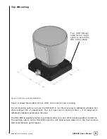
To p M o u n t i n g
Figure 4. HDL top mounting illustration.
Figure 4 shows the location of four .406” thru holes for top mounting.
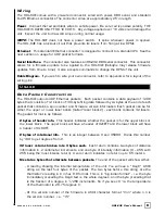
For all mounting options, be sure the HDL-64E is mounted securely to withstand vibration and
shock without risk of detachment. The unit need not be shock proofed — it is designed to
withstand standard automotive G-forces.
The HDL-64E is weatherproofed to withstand wind, rain, and other adverse weather conditions.
The spinning nature of the HDL-64E helps the unit shed excess water from the front window
that could hamper performance.
Four .406” through
holes for top mount
option to secure the
HDL to the vehicle.