


15
.
w w w . v e l o d y n e . c o m
HDL-64E User’s Manual
U t i l i z i n g t h e d b . X M L c a l i b r a t i o n d a t a f i l e i n D S R
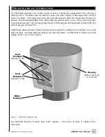
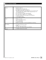
The db.XML file provided with your Velodyne HDL-64E contains all of the necessary data for the
proper alignment of the point cloud information gathered by the HDL sensor for each laser.
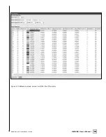
{vertical correction (deg), rotational correction (deg), distance correction (cm), vertical offset
(cm), horizontal offset (cm), minimum and maximum intensity (0-255)}.
When implemented properly, the image viewable from the Digital Sensor Recorder (DSR) will be
properly calibrated to provide an accurate visual representation of the environment in which the
sensor is being applied.
This data should also be used in any other program using the data generated by the HDL-64E.
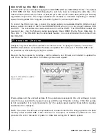
To i n t e g r a t e t h e d b . X M L f i l e i n t o t h e D S R p r o g r a m ,
— f o l l o w t h e s e s t e p s .
1. Provided that DSR has been installed on the host computer using the default settings,
follow this path: c:\program files\Digital Sensor Recorder
2. Cut and paste the existing db.XML file to another location and rename as the
default_db.XML
3. Copy and paste the db.XML file provided on the CD to the DSR program folder
previously opened
4. Close out the windows and the program is ready to run
5. Open the DSR program
6. Click options\properties
7. Check that the new values are present and that they reflect the values in the
example screen captures provided on the CD [Fig.6]
8. Your DSR viewer is now calibrated to your sensor