


3
.
w w w . v e l o d y n e . c o m
HDL-64E User’s Manual
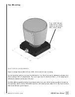
F r o n t / B a c k M o u n t i n g
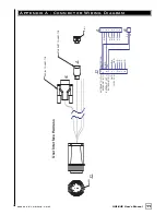
The HDL-64E base provides two mounting options: side mount and top mount. See Figure 2
for front/back mounting options, Figure 3 for side/side mounting, and Figure 4 for top
mounting instructions.
Figure 2. Front and back HDL mounting illustration.
See Figure 2. This figure shows the HDL-64E’s base plate screw locations with threaded inserts
for standard M8 hardware.
Ins tallation Ov ervie w
Four M8-1.25 x 12mm
deep mounting points.
(Four per side, for a
total of 16.)
Mounting
Base