


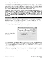

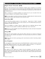


The HDL-64E data is presented as distances and intensities only. Velodyne includes a packet
viewer called DSR, whose installer files are on the CD that came with the unit. DSR reads in
the packets from the HDL-64E unit, performs the necessary calculations to plot the points
presented in 3-D space, and plots the points on the viewer screen.
Note:
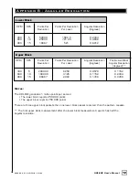
The HDL-64E will output three upper block packets for every one lower block packet.
This provides more resolution when identifying objects at greater distances.
The minimum return distance for the HDL-64E is approximately three feet.
Returns closer
than this should be ignored.
C o r r e c t i o n A n g l e s
Each HDL-64E laser is fixed with respect to vertical angle and offset to the rotational index data
provided in each packet. For each data point issued by the HDL-64E, rotational and horizontal
correction factors must be applied to determine the point’s location in 3-D space referred to by
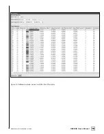
the return. Each HDL-64E unit comes with its own unique .XML file, called db.XML, that was
generated as a result of the calibration performed at Velodyne’s factory. DSR uses this XML
file to display points accurately. The .XML file also holds the key to interpreting the packet data
for users that wish to create their own interpretation and plotting routines.
db.XML contains 64 instances of the following five values used to interpret the packet data:
rotCorrection:
This parameter is the rotational correction angle for each laser, as
viewed from the back of the unit. Positive factors rotate to the left, and negative
values rotate to the right.
vertCorrection:
This parameter is the vertical correction angle for each laser, as
viewed from the back of the unit. Positive values have the laser pointing up, and
negative values have the laser pointing down.
distCorrection:
Each laser has its own unique distance due to minor variations in the
parts used to construct the laser. This correction factor, in centimeters, accounts
for this variance. This number should be directly added to the distance value read in
the packet.
vertoffsetCorrection:
This value represents the height of each laser as measured
from the bottom of the base. It is a fixed value for all upper block lasers and a
different fixed value for all lower block lasers.
horizOffsetCorrection:
This value represents the horizontal offset of each laser as
viewed from the back of the laser.
It is a constant positive or negative value for
all lasers.
Use the above values from the .XML file to calculate each point’s position in 3-D space. Use the
first 32 points for the upper block and the second 32 points for the lower block. The rotational
info found in the header is used to determine the packets position with respect to the 360
degree horizontal field of view.
Note:
There is a file on the CD called “HDL Source Example” that shows the calculations using
the above correction factors.
7
.
w w w . v e l o d y n e . c o m
HDL-64E User’s Manual