background image

VTSDIR 

21.03.2011 

©

Velleman nv 

7


How long do I preheat the PCB?  

Always preheat the PCB (up to 120°C or between 45 – 90 seconds) to allow the heat to conduct through 
to the component before introducing the top heat. With the 700W pre-heater the top of a small PCB will 
reach 120°C in approximately 45 – 90 seconds. Larger PCBs will take longer to pre-heat. To check the 
PCB/component temperature, use the hand-held IR temperature sensor to ‘look’ down at the 
PCB/component from about 60mm away and at about 45° angle.  


How long does it take to reach reflow temperature?  

After preheating the PCB up to 120°C, it should normally take about 30 – 45 seconds of heating with the 
IR hand tool to reach reflow temperature (200-220°C). It is not so easy to measure temperature during 
the reflow phase so therefore we use the electronic process timer to warn us when the reflow phase time 
is over. 

9.


Technical specifications 

mains power 

230VAC 

IR solderlight 

power 150W 

temperature range 

45 ~ 350°C 

time setting 

0 ~ 900s 

pre-heater 

power 650W 

temperature range 

100 ~ 350°C 

dimensions 

controller 

170 x 158 x 137 mm 

pre-heater 

280 x 90 x 260 mm 

weight ±7kg 

Use this device with original accessories only. Velleman nv cannot be held responsible in the event 
of damage or injury resulted from (incorrect) use of this device. 

The information in this manual is subject to change without prior notice. 

© 

COPYRIGHT NOTICE


The copyright to this manual is owned by Velleman nv.

 All worldwide rights reserved.  

No part of this manual or may be copied, reproduced, translated or reduced to any electronic medium or otherwise without 
the prior written consent of the copyright holder.  


Содержание VTSDIR

Страница 1: ...V IN US VTSD NFRA RE SER MAN DIR ED SMD UAL BGA RE EWORK S 3 STATION N ...

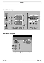
Страница 2: ...VTSDIR 21 03 2011 Velleman nv 2 Main station front panel Main station rear panel Figure ...

Страница 3: ...g th work BGA re ut first cons children Yo re to take t Always conne rd Be sure t uids or other e mains befo Death or se re nor use th move the AC eriod of time sed for sold manufacturer r intermitte hould be use back in its co le it is in the hand tool o your eyes s as serious VTSDIR 3 er man this produc e indicates th f the unit or cycling This ocal environ disposal au e manual tho r use it and ...

Страница 4: ...ture ng alloys use this type of s equirements king tempera f heat Do n n as burning ommencing m sult from el commencing y liquid to fa cal compone n and unaut d Quality W p this device from dust an shocks and ons of the de forbidden fo nty d purpose U rtain guidelin y for any ens this manual witch I So ounting up temperature temperature d tool power degrees Cels in degrees F for TIMER display Proc...

Страница 5: ... count the number of seconds that the IR heating was on Timer down operation Set the SOLDERLIGH TIMER switch 1 to the TIMER position O Set the Time counting switch 2 to the DOWN position O Set the timer using the 3 and 4 keys Press and hold 2s to increase setting speed Read the time in seconds on the display 9 Press on the footswitch to start IR heating release to stop IR heating The timer display...

Страница 6: ...r temperature herefore we seconds for soak about nent to cool e PCB holder pply a very s mponent PCB nd tool oper temperature herefore we ds for a smal soak about onent to coo cessary use al setting is IR Hand too reworking a g motion to se al setting is VTSDIR 6 GA componen mponent ering desold through a p de and mixe eflective cha gy is proved re below sho older positio ply a very sm te dependi ...

Страница 7: ...s not so easy to measure temperature during the reflow phase so therefore we use the electronic process timer to warn us when the reflow phase time is over 9 Technical specifications mains power 230VAC IR solderlight power 150W temperature range 45 350 C time setting 0 900s pre heater power 650W temperature range 100 350 C dimensions controller 170 x 158 x 137 mm pre heater 280 x 90 x 260 mm weigh...

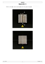
Страница 8: ...VTSDIR 21 03 2011 Velleman nv 8 Appendix 1 Remove screws X remove metal bar Y and remove plastic tubes Z ...

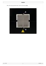
Страница 9: ...VTSDIR 21 03 2011 Velleman nv 9 Place the metal grid and secure it with the two screws X ...

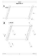
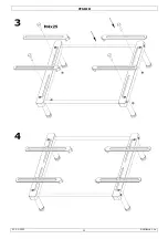
Страница 10: ...VTSDIR 21 03 2011 Velleman nv 10 Appendix 2 ...

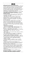
Страница 11: ...VTSDIR 21 03 2011 Velleman nv 11 ...

Страница 12: ...t or indirect damage caused after delivery to the article e g by oxidation shocks falls dust dirt humidity and by the article as well as its contents e g data loss compensation for loss of profits frequently replaced consumable goods parts or accessories such as batteries lamps rubber parts drive belts unlimited list flaws resulting from fire water damage lightning accident natural disaster etc fl...

Отзывы: