21
P
T
8.
•
•
•
.03.2011
Preparation
The proced
•
Switch
•
Set ‘co
•
Sort to
The followin
•
SMT Tw
•
Flux di
•
Low so
Temperatur
In normal o
system is d
150W short
maximum o
In normal u
provided by
Soldering
•
PREPARA
centre o
thicknes
apply so
o
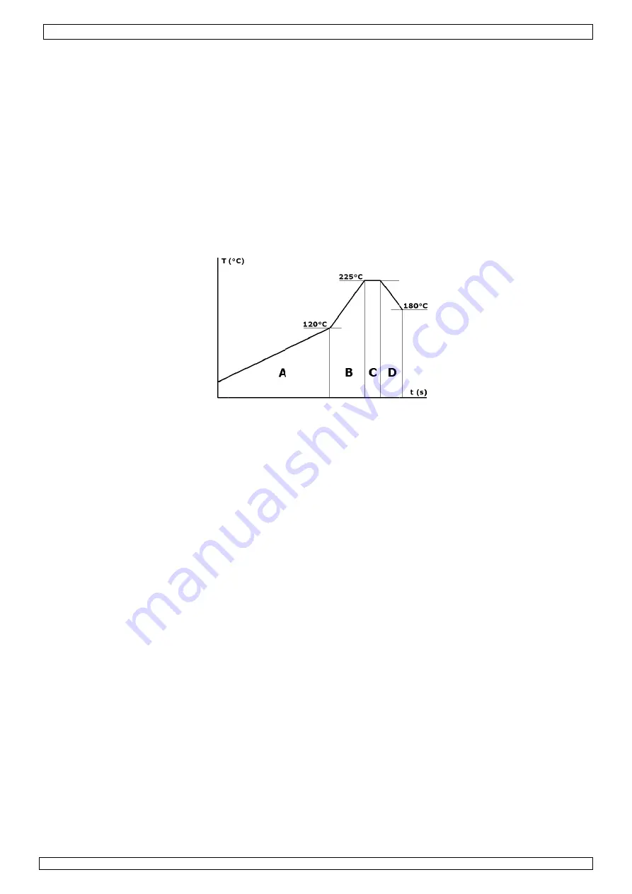
[A]
P
o
[B]
R
the c
durin
phase
o
[C]
S
o
[D]
C
Desolderin
•
PREPARA
centre o
o
[A]
P
o
[B]
R
the c
durin
time
o
[C]
S
o
[D]
C
Aftercare
•
Clean flu
•
Check so
•
Test
.
Q&A
What Top H
Between
What’s the
Approxim
Move th
compone
What pre-h
Between
n
ure for prep
h on and war
ontrol setting
ools and flux
ng tools are
weezers, fin
ispenser bot
olids and gel
re profile
operation the
esigned for
t wave IR lam
of 650W med
use, approxim
y the back h
ATION: plac
of the PCB pr
ss). Place an
older paste to
PREHEAT the
REFLOW: use
omponent u
ng the reflow
e time (norm
SOAK for a s
COOL: allow
ng
ATION: plac
of the PCB pr
PREHEAT the
REFLOW: use
omponent u
ng the reflow
(normally 3
SOAK for a s
COOL – allow
ux residue of
older joints
Heat setting
n 220 and 38
working dist
mately 5~10
e hand tool
ent.
eater setting
n 200 and 29
aring to rew
rm up.
gs’ required
xes required.
required for
e tipped
ttle
/paste flux
e component
rework sing
mp focused
dium wave I
mately 25%
eater (pre-h
e the PCB in
re-heater. Fo
d align comp
o the PCB be
e fluxed com
e the IR han
p to reflow t
w phase so th
mally 30-45
short period
the compon
e PCB in the
re-heater. Ap
e fluxed com
e the IR han
p to reflow t
w phase so th
0-45 second
short period
w the compo
ff PCB if nec
should you u
80°C. Norma
tance of the
0 mm when
in a scannin
g should I us
90°C. Norma
work SMT/BG
for PCB/com
.
r use in solde
t is first put
le/double sid
through a re
IR.
of the energ
heater). Figu
n the PCB ho
or BGAs, app
ponent.
Not
efore placing
mponent/PCB
nd tool (oper
temperature
herefore we
seconds for
soak (about
nent to cool
e PCB holder
pply a very s
mponent/PCB
nd tool (oper
temperature
herefore we
ds for a smal
soak (about
onent to coo
cessary
use?
al setting is
IR Hand too
reworking a
g motion to
se?
al setting is
VTSDIR
6
GA componen
mponent
ering/desold
through a p
de and mixe
eflective cha
gy is proved
re below sho
older, positio
ply a very sm
te
– dependi
g component
B to approxim
rated by pre
e (200-225°C
use the time
a small PCB
t 10 seconds
to below 18
r, positioning
small amoun
B to approxim
rated by pre
e (200-225°C
use the time
ll PCB).
t 10 seconds
l to below 18
240°C.
ol and how d
nd move up
heat leads,
240°C.
nts is as follo
dering operat
preheat stage
d technology
amber system
d by the top
ows how the
ning the com
mall amount
ng on the ap
t.
mately 120°C
ssing the foo
C). It is not
er on the IR
B).
s) the compo
0°C before m
g the compon
nt of flux und
mately 120°C
ssing the foo
C). It is not
er on the IR8
s) the compo
80°C before
do I move it
to 30mm w
taking abou
ows:
tions:
e, followed b
y PCB. The t
m. The botto
heater, and
e energy is a
mponent site
of gel flux (
pplication, y
C (as measu
otswitch) for
so easy to m
810 control
onent allowin
moving the P
nent site to
der/around t
C (as measu
otswitch) for
so easy to m
810 controlle
onent allowin
moving the
for rework?
when removin
ut one secon
by a reflow s
top heat is d
om heater de
75% of the
applied to a c
e to be rewo
(approx. 0.1
you may be r
ured by the I
r the reflow
measure tem
ler to limit t
ng the joints
PCB.
be reworked
the compone
ured by the I
r the reflow
measure tem
er to limit th
ng the joints
PCB.
ng compone
d for each sc
©
Velleman
stage. The
derived from
elivers a
energy is
component.
rked over th
- 0.15mm)
required to
IR sensor).
phase to hea
mperature
he reflow
s to fully bon
d over the
ent.
IR sensor).
phase to hea
mperature
he reflow pha
s to fully bon
nts.
can of the
n nv
a
he
at
nd.
at
ase
nd.
Содержание VTSDIR
Страница 1: ...V IN US VTSD NFRA RE SER MAN DIR ED SMD UAL BGA RE EWORK S 3 STATION N ...
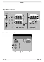
Страница 2: ...VTSDIR 21 03 2011 Velleman nv 2 Main station front panel Main station rear panel Figure ...
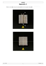
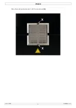
Страница 9: ...VTSDIR 21 03 2011 Velleman nv 9 Place the metal grid and secure it with the two screws X ...
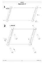
Страница 10: ...VTSDIR 21 03 2011 Velleman nv 10 Appendix 2 ...
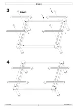
Страница 11: ...VTSDIR 21 03 2011 Velleman nv 11 ...


