background image

DVM13MFC                                                                                                                                                VELLEMAN 

3

1.  power switch 

: Press the button once to turn the device on (depressed position) 

and press again to turn it off. 

2.  HOLD button 

: Press this button to toggle in and out of the data-hold mode. 

3.  RESET button 

: The eight LED indicators and all segments of the display are lit 

immediately when RESET is pressed and the device automatically 
switches to the 10MHz frequency range. 

4.  CHECK button 

: Press CHECK. All segments of the display are lit in the following 

order : 0 

 9, “

”, the LEDs of the functions printed on the display. 

5.  A.TOT 

: Press the A.TOT button to switch to the total measurement mode. 

6.  A.PERI 

: Press this button to install the period measurement mode. 

7.  G.TIME 

: This buttons is used to adjust the gate time in the frequency mode. 

In the period mode, this button is used to install the multiplier 
factor : 


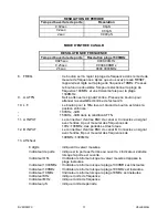
CHANNEL A INPUT MODE 


FREQUENCY RESOLUTION 

Gate Time 

10MHz Range Resolution 

100MHz Range Resolution 

0.02sec. 00000.0KHz 

000.000MHz 

0.2sec. 00000.00KHz 

000.0000MHz 

2sec. 00000.000KHz 

000.00000MHz 


PERIOD RESOLUTION 

Gate Time 

Resolution 

0.02sec. 

0.0

µ

0.2sec. 

0.00

µ

2sec. 

0.000

µ


CHANNEL B INPUT MODE 


FREQUENCY RESOLUTION 

Gate Time 

1300MHz Range Resolution 

0.025sec. 0000.00MHz 

0.25sec. 0000.000MHz 

2.5sec. 0000.0000MHz 

 
8.  FREQ. 

: Used to select the frequency range in the frequency mode. Press 

RESET to select the 10MHz frequency range. Press again to 
select the 100MHz frequency range and press a third time for the 
1300MHz frequency range. 

9.  A.ATTN 

: This button attenuates the input signal. Press it to attenuate the 

input signal sensitivity by a factor of 20. 

10.  L.F. 

: Low-pass filter button. When the button is pressed in: 

- 100KHz, -3dB 
-  150KHz, -3dB at ATTN condition 

Содержание DVM13MFC

Страница 1: ...issing or damaged 3 Safety Prescriptions Injury or death can occur even with low voltages and low current It is extremely important that you read these safety instructions before using your device Fol...

Страница 2: ...all times 8 Never apply more than 250V between the A input and earth ground Never apply more than 3V between input B and earth ground 9 Do not calibrate or service the device unless a qualified techn...

Страница 3: ...quency mode In the period mode this button is used to install the multiplier factor CHANNEL A INPUT MODE FREQUENCY RESOLUTION Gate Time 10MHz Range Resolution 100MHz Range Resolution 0 02sec 00000 0KH...

Страница 4: ...e unit of frequency MHz Indicator indicates the unit of frequency S Indicator indicates the unit of period 5 Back Panel Description 1 Power Input with Fuse Check whether the power source is compatible...

Страница 5: ...onnect the input signal with BNC connector A on the front panel 5 Put A ATTN in the desired position Press A ATTN is the input signal 300mV it reduces the number of mistakes since the triggering sensi...

Страница 6: ...e Error short term stability 5 x 10 6 minute Max accuracy is achieved during a one year period after calibration Ideal circumstances require a temperature of 18 to 28 C 64 to 82 F and a max relative h...

Страница 7: ...ean the terminals as follows 1 Turn off the device 2 Unplug the power cord 3 Remove the test leads from the input terminals 4 Shake out any dirt that may be present in the terminals Have the device se...

Страница 8: ...akking beschadigd of onvolledig is 3 Veiligheidsvoorschriften Zelfs bij een lage spanning of stroom kunnen zich dodelijke ongevallen voordoen Het is zeer belangrijk om deze veiligheidsvoorschriften te...

Страница 9: ...ische compatibiliteit en 73 23 EEC laagspanning zoals gewijzigd door 93 68 EEC CE label Symbolen 4 Beschrijving Frontpaneel zie figuur blz 2 1 voedingsschakelaar Druk 1 x op de knop om het toestel in...

Страница 10: ...rzwakker voor het ingangssignaal Druk deze knop in om de ingangssignaalgevoeligheid te verzwakken met factor 20 10 L F Knop voor low pass filter Wanneer de knop is ingedrukt 100KHz 3dB 150KHz 3dB in d...

Страница 11: ...al U kunt het gebruiken als referentiesignaal voor een andere frequentieteller Respecteer altijd een uitgangsimpedantie van 50 wanneer u het uitgangssignaal 10MHz gebruikt 4 GND aansluiting 6 Metingen...

Страница 12: ...aats de HOLD knop in de ingedrukte stand en lees het totaal af van de display d Check mode Dankzij de self check mode kunt u de werking van het toestel controleren met uitzondering van de ingangen de...

Страница 13: ...1 digit 5 x 10 6 x frequentie minuut Periodemetingen Kanaal Bereik Resolutie Nauwkeurigheid A enkel 0 1S tot 0 1 S 10Hz tot 10MHz 0 0 S 0 00 S 0 000 S selecteerbaar 1 digit 1 x 10 5 x periode maand 1...

Страница 14: ...n zekering door een identiek exemplaar of een zekering met dezelfde specificaties 5 Zekering snel 200mA 250V 5 x 20mm De inhoud en specificaties van deze handleiding kunnen worden gewijzigd zonder voo...

Страница 15: ...tements secs pour isoler votre corps du sol Utilisez des paillassons en caoutchouc des mat riaux d isolation agr s et portez des chaussures avec des semelles en caoutchouc 4 Pendants vos mesures vous...

Страница 16: ...llument dans l ordre suivant 0 9 LEDs des fonctions que l on voit sur l cran 5 A TOT Pressez ce bouton A TOT pour activer le mode de mesure des totaux 6 A PERI Pressez ce bouton A TOT pour activer le...

Страница 17: ...osition enfonc e 100KHz 3dB 150KHz 3dB dans la condition ATTN 11 A INPUT Le connecteur d entr e BNC de canal A Connectez un signal avec l entr e A pour mesurer des fr quences de 10Hz 100MHz des p riod...

Страница 18: ...cordons de mesure et assurez vous que les fiches de c ble sont compatibles avec les jacks de l appareil L appareil ne peut pas tre utilis s il y a un probl me avec un des facteurs susmentionn s a Mes...

Страница 19: ...2 S lectionnez le mode autocontr le avec le bouton CHECK 3 Pressez CHECK Tous les segments de l afficheur s allument dans l ordre suivante 0 9 LEDs des fonctions imprim es sur la fen tre de l afficheu...

Страница 20: ...ement 0 1S 0 1 S 10Hz 10MHz 0 0 S 0 00 S 0 000 S s lectionnable 1 digit 1 x 10 5 x p riode mois 1 digit 5 x 10 6 x p riode minute Mesures de totaux Canal Plage R solution A uniquement 10Hz 10MHz 1 dig...

Страница 21: ...ctez les pointes de touche des connexions d entr e 4 Remplacez le fusible saut par un exemplaire identique ou par un fusible aux m mes sp cifications 5 Le fusible rapide 200mA 250V 5 x 20mm Le contenu...

Страница 22: ...corriente que podr an estar puestos a tierra Tenga su cuerpo aislado usando ropa seca zapatos de goma o cualquier otro material de aislamiento aprobado 4 Nunca toque cables o conexiones expuestas el...

Страница 23: ...por el siguiente orden 0 9 LEDs de funciones que se ven en la pantalla 5 A TOT Apriete este bot n para activar el modo de medici n de los totales 6 A PERI Apriete este bot n para activar el modo de m...

Страница 24: ...t en la posici n apretada 100KHz 3dB 150KHz 3dB en la condici n ATTN 11 A INPUT El conector de entrada BNC de canal A Conecte una se al a la entrada A para medir frecuencias de 10Hz 100MHz periodos y...

Страница 25: ...ue los conectores del cable son compatibles con los jacks del aparato No use el aparato si tiene un problema con uno de los siguientes factores a Medir la frecuencia 1 Apriete el bot n POWER para acti...

Страница 26: ...Todos los segmentos de la pantalla se iluminan por el siguiente orden 0 9 LEDs de funciones impresos en el display 4 Apriete RESET para salir del modo autocontrol 7 Especificaciones Especificaciones...

Страница 27: ...de 10Hz a 10MHz 0 0 S 0 00 S 0 000 S seleccionable 1 d gito 1 x 10 5 x periodo mes 1 d gito 5 x 10 6 x periodo minuto Mediciones de totales Canal Rango Resoluci n A s lo de 10Hz a 10MHz 1 d gito Carac...

Страница 28: ...entaci n 3 Desconecte las puntas de prueba de las conexiones de entrada 4 Reemplace el fusible fundido por un fusible del tipo requerido o un fusible con especificaciones id nticas 5 El fusible r pido...

Страница 29: ...mit der Erde verbunden sind Tragen Sie w hrend Messungen trockene Kleidung als Schutz Tragen Sie Schuhe mit Gummisohlen und oder legen Sie eine Gummimatte oder genehmigtes Isolierungsmaterial unter de...

Страница 30: ...euchten in dieser Reihenfolge 0 9 LEDs der Funktionen die auf dem Display stehen 5 A TOT Dr cken Sie die A TOT Taste um auf den Impulsz hler umzuschalten 6 A PERI Dr cken Sie diese Taste um die Period...

Страница 31: ...B in der ATTN Position 11 A INPUT BNC Eingangssteckverbinder des Kanals A Bringen Sie ein Signal an Eingang A an um Frequenzen von 10Hz 100MHz und auch Perioden und Impulszahl zu messen 12 B INPUT BNC...

Страница 32: ...beh r nicht besch digt defekt oder schmutzig sind z B Fett berpr fen Sie die Isolierung der Messleitungen und vergewissern Sie sich davon dass die Netzleitung exakt in die Netzanschlussbuchse des Ger...

Страница 33: ...eit der Zeitbasis und dem Zeitbasisteiler die im Periodenmodus verwendet wurden 1 Dr cken Sie den EIN AUS Schalter um das Ger t einzuschalten 2 W hlen Sie den Selbstkontrolle Modus mit der CHECK Taste...

Страница 34: ...pulsz hler Kanal Bereich Aufl sung A nurl 10Hz bis 10MHz 1 Digit Eigenschaften der Eing nge Kanal A Eingangsempfindlichkeit 10MHz Bereich 10Hz bis 8MHz 25mVrms 8MHz bis 10MHz 50mVrms Eingangsempfindli...

Страница 35: ...eine Sicherung ersetzen m ssen Trennen Sie das Kabel und eventuelle Messleitungen von aller Spannungsquellen und ersetzen Sie sie danach durch eine neue gleichen Typs Sicherung ersetzen 1 Schalten Si...

Отзывы: