background image

5

Contents

VEGAPULS SR 68 • 4 … 20 mA/HART two-wire

38294-EN-130624

9.1 Maintenance .................................................................................................................. 59

9.2  Measured value and event memory ............................................................................... 59

9.3  Asset Management function ........................................................................................... 60

9.4  Rectify faults ................................................................................................................... 63

9.5  Exchanging the electronics module ................................................................................ 66

9.6  Software update ............................................................................................................. 67

9.7  How to proceed in case of repair .................................................................................... 67

10 Dismounting

10.1  Dismounting steps.......................................................................................................... 68

10.2 Disposal ......................................................................................................................... 68

11 Supplement

11.1  Technical data ................................................................................................................ 69

11.2 Dimensions .................................................................................................................... 76

Safety instructions for Ex areas

Please note the Ex-specific safety information for installation and op-

eration in Ex areas. These safety instructions are part of the operating 

instructions manual and come with the Ex-approved instruments.
Editing status: 2013-05-16

Содержание VEGAPULS SR 68

Страница 1: ...Operating Instructions Radar sensor for continuous level measurement of bulk solids VEGAPULS SR 68 4 20 mA HART two wire Document ID 38294...

Страница 2: ...For further information see chapter Mounting 1 Make sure that the power supply corresponds to the specifica tions on the type label 2 Connect the instrument according to the following illustration 5 1...

Страница 3: ...1 m 39 37 35 m 1378 Fig 3 Parameterization example 1 Min level max meas distance 2 Max level min meas distance For this adjustment the distance is entered for min and max level If these values are no...

Страница 4: ...ounting preparations Parabolic antenna 14 4 3 Mounting preparations Horn antenna 15 4 4 Mounting instructions 16 5 Connecting to power supply 5 1 Preparing the connection 30 5 2 Connecting 31 5 3 Wiri...

Страница 5: ...e update 67 9 7 How to proceed in case of repair 67 10 Dismounting 10 1 Dismounting steps 68 10 2 Disposal 68 11 Supplement 11 1 Technical data 69 11 2 Dimensions 76 Safety instructions for Ex areas P...

Страница 6: ...personnel and put into practice by them 1 3 Symbolism used Information tip note This symbol indicates helpful additional information Caution If this warning is ignored faults or malfunctions can resu...

Страница 7: ...t instrument complying with all prevailing regulations and guidelines The instrument must only be operated in a technically flawless and reliable condition The operator is responsible for the trouble...

Страница 8: ...ions are accepted as the standard in field instrumentation The device fulfills the requirements of the following NAMUR recom mendations NE 21 Electromagnetic compatibility of equipment NE 43 Signal le...

Страница 9: ...That is why we have introduced an environment management system with the goal of continuously improving company environmental pro tection The environment management system is certified according to DI...

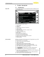
Страница 10: ...nstrument documentation 14 Reminder to observe the instrument documentation 15 Notified authority for CE marking 16 Approval directive With the serial number of the instrument on the type label you ca...

Страница 11: ...e radar sensor emits short radar pulses with a duration of approx 1 ns These pulses are reflected by the product and received by the antenna as echoes The transit time of the radar pulses from emissio...

Страница 12: ...le instruments to the USB interface of a PC For parameter adjustment of these instruments the adjustment software PACTware with VEGA DTM is required You can find further information in the operating i...

Страница 13: ...in the supplementary instructions manual Flanges according to DIN EN ASME JIS Document ID 31088 The electronics module VEGAPULS series 60 is a replacement part for radar sensors of VEGAPULS series 60...

Страница 14: ...nstrument exposed to the process are suitable for the existing process conditions These are mainly Active measuring component Process fitting Process seal Process conditions are particularly Process p...

Страница 15: ...e max 40 Nm Note On the version with rinsing air connection make sure that the holes in the antenna and in the process fitting coincide This ensures a suf ficient air flow the air is led through the h...

Страница 16: ...g the marking specifies the position of the polarisation of the radar signal 3 4 1 2 Fig 6 Dismounting of the horn antenna 1 Marking for the polarisation 2 Marking at the antenna socket 3 Hexagon scre...

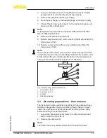
Страница 17: ...you should carry out a false signal storage during setup This applies particularly if buildup on the vessel wall is expected In such a case it is recommended to repeat the false signal storage at a l...

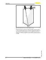
Страница 18: ...flowing medium With bulk solids silos with lateral pneumatic filling mounting should not be in the filling stream as the microwave signal will be interferred The optimum mounting position is next to t...

Страница 19: ...S SR 68 4 20 mA HART two wire 38294 EN 130624 Fig 10 Mounting of the radar sensor with inflowing medium The socket piece should be dimensioned in such a way that the antenna end protrudes slightly out...

Страница 20: ...ntenna 10 mm 0 39 Fig 12 Recommended socket mounting with parabolic antenna When using a swivelling holder keep in mind that the distance between antenna and socket gets smaller as the inclination of...

Страница 21: ...tween antenna and socket with parabolic antenna If the medium has good reflective properties VEGAPULS SR 68 with horn antenna can also be mounted on a longer socket piece Recommended values for socket...

Страница 22: ...htly out of the end of the mounting socket Due to the antenna extension however disturbing reflections are generated in the close up range This can lead to an increase in the required minimum distance...

Страница 23: ...r r r 1 3 1 2 Fig 16 Orientation If mounting in the centre of the silo is not possible the sensor can be directed to the vessel center by using the optional swivelling holder The following description...

Страница 24: ...between installation position and vessel centre dependent on the measuring distance for inclination angles of 2 10 Distance d m 2 4 6 8 10 2 0 1 0 1 0 2 0 3 0 4 4 0 1 0 3 0 4 0 6 0 7 6 0 2 0 4 0 6 0 8...

Страница 25: ...ting spi rals struts etc can cause false echoes and impair the useful echo Make sure when planning your measuring site that the radar sensor has a clear view to the measured product In case of existin...

Страница 26: ...e sensors are designed for relatively slow level changes When using VEGAPULS SR 68 on a movable bracket the max measuring rate must be observed see chapter Technical data Instruments for a temperature...

Страница 27: ...om For this application the minimal amounts of stray radiation from the sensor can be reflected and strengthened by the walls of the subsur face enclosures In the case of sensors with plastic housings...

Страница 28: ...outer wall of the silo with the sensor directed towards the emptying aperture in the silo center Fig 23 Mounting of VEGAPULS SR 68 in multiple chamber silos Fig 24 Orientation of VEGAPULS SR 68 for e...

Страница 29: ...ng air connection The air is distributed via channels in the antenna system and keeps it largely free of dust Fig 25 Purging air connection with horn antenna Fig 26 Purging air connection with parabol...

Страница 30: ...ich is above the test values of EN 61326 1 for industrial areas screened cable should be used For instruments with housing and cable gland use cable with round cross section A cable outer diameter of...

Страница 31: ...ith external electronics via the screen of the special connection cable You can find specifications on the potential connections inside the instrument in chapter Technical data 5 2 Connecting The volt...

Страница 32: ...s are insert ed directly into the terminal openings In case of flexible cores without end sleeves press the terminal from above with a small screwdriver the terminal opening is freed When the screwdri...

Страница 33: ...1 2 6 7 8 4 20mA 2 3 4 1 Fig 29 Electronics and connection compartment single chamber housing 1 Voltage supply signal output 2 For display and adjustment module or interface adapter 3 For external di...

Страница 34: ...ble chamber housing 1 Voltage supply Signal output 2 For display and adjustment module or interface adapter 3 Ground terminal for connection of the cable screen 1 Bus USB Status Test SIM Card 1 2 Fig...

Страница 35: ...ment 2 For display and adjustment module or interface adapter 3 Internal connection to the plug connector for external display and adjust ment unit optional Note If an instrument with Ex d ia approval...

Страница 36: ...n 1 2 Pin 2 3 Pin 3 4 Pin 4 Contact pin Colour connection ca ble in the sensor Terminal electronics module Pin 1 Brown 5 Pin 2 White 6 Pin 3 Blue 7 Pin 4 Black 8 5 6 Wiring plan version IP 66 IP 68 1...

Страница 37: ...ectronics Indication of the instrument type hardware and software version measurement loop name on the display or PC Indication of the status message F 105 Determine measured value on the display or P...

Страница 38: ...t necessary to interrupt the power supply Proceed as follows 1 Unscrew the housing cover 2 Place the display and adjustment module in the requested posi tion onto the electronics and turn to the right...

Страница 39: ...ctronics compartment 2 In the connection compartment with Ex d ia version not possible Note If you intend to retrofit the instrument with a display and adjustment module for continuous measured value...

Страница 40: ...ted to the application conditions The parameter adjustment is carried out via an adjustment menu The main menu is divided into five sections with the following func tions Setup Settings e g for measur...

Страница 41: ...ration material cone and additional echoes from the vessel wall To adapt the sensor to these different measuring conditions the selection Liquid or Bulk solid should be made in this menu item Through...

Страница 42: ...sel small laterally mounted or large top mounted stirrer Process measurement conditions Relatively smooth product surface Max requirement to the measurement accuracy Condensation Slight foam generatio...

Страница 43: ...oduct speed Fast up to slow filling with short up to long bypass tube possible Often the level is hold via a control facility Vessel Lateral outlets and inlets Joins like flanges weld joints Shifting...

Страница 44: ...Gauge rate of change slow gauge change Process measurement conditions Ice and condensation on the antenna possible Spiders and insect nestle in the antennas Turbulent water surface Sensor flooding po...

Страница 45: ...lations present Process measurement conditions Measured value jumps e g by truck loading Large distance to the medium Large angles of repose Heap Sensor mounting on movable conveyor belts Detection of...

Страница 46: ...riate keys save your settings with OK and jump to the next menu item with the ESC and the key Also the vessel form can influence the measurement apart from the medium and the application To adapt the...

Страница 47: ...By means of these settings the real level will be calculated The real product level during this adjustment is not important be cause the min max adjustment is always carried out without chang ing the...

Страница 48: ...distance value 4 Enter the appropriate distance value in m corresponding to the percentage value for the full vessel Keep in mind that the max level must lie below the min distance to the antenna edg...

Страница 49: ...menu with zoom functions is opened X Zoom Zoom function for the meas distance Y Zoom 1 2 5 and 10x signal magnification in dB Unzoom Reset the presentation to the nominal measuring range with single m...

Страница 50: ...ering reflections can be detected Proceed as follows 1 Select the menu item Additional settins with and confirm with OK With you have to select the menu item False signal suppression and confirm with...

Страница 51: ...ed at the time of setup This is generally recommended for using the As set Management functions it is absolutely necessary If possible the curve should be saved with a low level in the vessel With the...

Страница 52: ...ion user programmable linearization curve as well as the measured value memory will be deleted Basic settings Resetting the parameter settings incl special pa rameters to the default values of the res...

Страница 53: ...Max Min current 3 8 mA max current 20 5 mA Block adjustment Released Display Language Like order Displayed value Distance Display unit m Scaling size Volume l Scaling 0 00 lin 0 l 100 00 lin 100 l Bac...

Страница 54: ...dule are saved All data of the menu Setup and Display In the menu Additional adjustments the items Sensor specific units temperature unit and linearization The values of the user programmable lineariz...

Страница 55: ...nce 250 optional depending on processing 3 Connection cable with 2 mm pins and terminals 4 Processing system PLC Voltage supply 5 Interface adapter for example VEGACONNECT 4 Note With power supply uni...

Страница 56: ...download the latest instrument software from our homepage A description of the update procedure is also available in the Internet Further setup steps are described in the operating instructions manu...

Страница 57: ...is of the saved measured value and echo curves The standard version is available as a download under www vega com downloads and Software The full version is avail able on CD from the agency serving yo...

Страница 58: ...descriptions as Enhanced Device Description EDD are available for DD adjustment programs such as for example AMS and PDM The files can be downloaded at www vega com downloads under Software 8 2 Field...

Страница 59: ...mperature When the instrument is shipped the measured value memory is active and stores distance measurement certainty and electronics temperature every 3 minutes The requested values and recording co...

Страница 60: ...are divided into the following categories Failure Function check Out of specification Maintenance requirement and explained by pictographs 4 1 2 3 Fig 45 Pictographs of the status messages 1 Failure r...

Страница 61: ...d ing to the limit values dif ference between min and max 10 mm F025 Error in the linearization table Index markers are not con tinuously rising for examle unlogical value pairs Check linearization ta...

Страница 62: ...ltage briefly The following table shows the error codes and text messages in the status message Function check and provides information on causes as well as corrective measures Code Text mes sage Caus...

Страница 63: ...rdware defect Check connections Exchanging the electronics Send instrument for repair M505 No echo avail able Level echo can no longer be detected Clean the antenna Use a more suitable antenna sensor...

Страница 64: ...ssary Current sig nal greater than 22 mA or less than 3 6 mA Electronics module in the sensor defec tive Exchange the instrument or send it in for repair The below tables show typical examples for app...

Страница 65: ...duct type dished end high dielectric figure adapt if necessary The level echo cannot be distin guished from the false echo at a false echo position jumps to multiple echo Remove reduce false echo mini...

Страница 66: ...er Medium type and adapt if necessary Optimize installation position and sensor orientation Reflections from the product surface via the vessel wall deflection Depending on the reason for the fault an...

Страница 67: ...m downloads and Software You can find information about the installation in the download file Caution Instruments with approvals can be bound to certain software ver sions Therefore make sure that the...

Страница 68: ...ling companies We use recyclable materials and have designed the parts to be easily separable Correct disposal avoids negative effects on humans and the environ ment and ensures recycling of useful ra...

Страница 69: ...g precision casting silicone aluminium plastic housing stainless steel housng electropolished Inspection window in housing cover optional Polycarbonate Ground terminal 316L Ohmic contact Between groun...

Страница 70: ...48 mm 1 89 in up to 20 m 65 62 ft 75 mm 2 953 in 95 mm 3 74 in up to 30 m 98 43 ft Parabolic antenna up to 30 m 98 43 ft Output variable Output signal 4 20 mA HART Range of the output signal 3 8 20 5...

Страница 71: ...eflector False reflections Biggest false signal 20 dB smaller than the useful signal Deviation with liquids See following diagrams 1 0 m 3 28 ft 10 mm 0 394 in 2 mm 0 079 in 2 mm 0 079 in 10 mm 0 394...

Страница 72: ...power density 14 dBm MHz EIRP Max spectral transmission power density 43 dBm 50 MHz EIRP Max power density in a distance of 1 m 1 W cm Ambient conditions Ambient storage and transport tempera ture 40...

Страница 73: ...enna 1 g at 5 200 Hz according to EN 60068 2 6 vibration with resonance Shock resistance Horn antenna 100 g 6 ms according to EN 60068 2 27 mechanical shock Parabolic antenna 25 g 6 ms according to EN...

Страница 74: ...gland with integrated connec tion cable M20 x 1 5 cable 5 9 mm Cable entry NPT Blind plug M20 x 1 5 NPT Connection cable Wire cross section 0 5 mm AWG 20 Wire resistance 0 036 m Tensile strength 1200...

Страница 75: ...instrument for 9 6 V UB 14 V 0 7 Veff 16 400 Hz for 18 V UB 36 V 1 0 Veff 16 400 Hz Permissible residual ripple Ex d ia instrument for 18 V UB 36 V 1 Veff 16 400 Hz Load resistor Calculation UB Umin...

Страница 76: ...Dimensions The following dimensional drawings represent only an extract of all possible versions Detailed dimensional drawings can be downloaded at www vega com downloads under Drawings Plastic housi...

Страница 77: ...ed display and adjustment module the housing is 9 mm 0 35 in higher 1 Single chamber version 2 Double chamber version Aluminium housing in protection rating IP 66 IP 68 1 bar 120 mm 4 72 105 mm 4 13 1...

Страница 78: ...chamber version electropolished 2 Single chamber version precision casting 2 Double chamber version precision casting Stainless steel housing in protection rating IP 66 IP 68 1 bar 117 mm 4 61 103 mm...

Страница 79: ...readed version mm inch 38 mm 1 50 22 mm 0 87 22 mm 0 87 SW 46 mm 1 81 8 50 16 93 3 94 1 58 1 89 2 95 3 74 4 72 x y 100 40 120 48 216 75 430 95 1 2 3 4 x y 1 2 3 4 x y G1 A 1 NPT x y 2 1 144 mm 5 67 Fi...

Страница 80: ...ULS SR 68 horn antenna in flange version x y 2 1 165 mm 6 5 60 mm 2 36 mm inch 8 50 16 93 3 94 1 58 1 89 2 95 3 74 4 72 x y 100 40 120 48 216 75 430 95 1 2 3 4 x y 1 2 3 4 Fig 63 VEGAPULS SR 68 horn a...

Страница 81: ...velling holder mm inch 2 0 m m 0 7 9 2 0 m m 0 7 9 3 94 1 58 1 89 2 95 3 74 4 72 8 50 16 93 x y x y 1 x y 100 40 120 48 216 75 430 95 1 2 3 4 x y 1 2 3 4 4 0 m m 1 5 8 1 4 6 m m 5 7 5 2 max 15 0 59 Fi...

Страница 82: ...8294 EN 130624 VEGAPULS SR 68 parabolic antenna and swivelling holder 1 3 0 m m 5 1 2 243 mm 9 57 1 4 0 m m 1 5 8 max 15 0 59 1 2 0 m m 4 7 2 2 Fig 65 VEGAPULS SR 68 parabolic antenna and swivelling h...

Страница 83: ...werbliche Schutzrechte N here Informationen unter www vega com Les lignes de produits VEGA sont globalement prot g es par des droits de propri t intellec tuelle Pour plus d informations on pourra se r...

Страница 84: ...ctronics and connection compartment single chamber housing 33 Electronics compartment double chamber housing 33 Electronics compartment with Ex d double chamber housing 35 Error messages 60 Event memo...

Страница 85: ...85 INDEX VEGAPULS SR 68 4 20 mA HART two wire 38294 EN 130624 Subsurface enclosure 27 T Type plate 10 V Vessel form 46 Vessel height 46 Vessel installations 25 Vessel insulation 26 Voltage supply 30...

Страница 86: ...86 Notes VEGAPULS SR 68 4 20 mA HART two wire 38294 EN 130624...

Страница 87: ...87 Notes VEGAPULS SR 68 4 20 mA HART two wire 38294 EN 130624...

Страница 88: ...of delivery application practical use and operat ing conditions of the sensors and processing systems correspond to the information available at the time of printing Subject to change without prior n...

Отзывы: