background image

4

VEGADIS 371 Ex

Product description

1.5 Technical data

General

Series

instrument for front panel or wall mounting or
mounting on rail 35 x 7,5

Dimensions

W = 96 mm, H = 104 mm, D = 90 mm

Weight

approx. 400 g

Housing material

plastic ABS/POM

Cross section area of conductor

max. 2,5 mm

2

Ambient conditions

Permissible ambient temperature

-20°C … +60°C

Storage and transport temperature

-40°C … +85°C

Temperature error

0,01 %/K

Electrical protective measures

Protection class

II

Overvoltage category

II

Protection
- wall or carrier rail mounting

IP 20

- front panel mounting

IP 40

Voltage supply

Supply voltage

20 … 250 V AC/DC

Power consumption

4 W, 12,5 VA

Sensor input (floating)

Transmission

analogue

Connection line to the sensor

2-wire

I

active

- sensor supply

25 … 15 V (range 4 ... 20 mA)

- shortcircuit limitation

approx. 30 mA

I

passive

- inner resistance

< 250

 Ω

 (range 4 ... 20 mA)

U
- inner resistance

> 100 k

Ω

 (range 0 ... 10 V)

Current output 0/4 … 20 mA (signal circuit, floating)

Resolution

0,1 % (range 0/4 ... 20 mA)

max. load

500 

Ω

Fault signal

approx. 22 mA

Linearity error

0,1 %

Relay output

Number of relays

4 (2 modules with 2 relays each)

Turn-on voltage

min. 10 mV
max. 250 V AC, 250 V DC

Switching current

min. 10 

μ

A

max. 3 A AC, 1 A DC

Breaking capacity

max. 54 W DC, 500 VA AC

Indication of switching condition

LED lights - relay energized
LED off - relay deenergized

Digital indication

Zero point (4 mA or 0 V)

-9999 … 9999

Final point (20 mA or 10 V)

-9999 … 9999

Decimal point

individually selectable

Содержание VEGADIS 371 Ex

Страница 1: ...8888 Operating Instruction VEGADIS 371 Ex VEGADIS 371 Ex 16 85 ...

Страница 2: ...duct description 1 1 Function and configuration 3 1 2 Types and versions 3 1 4 Dimensions 3 1 3 Approvals 3 1 5 Technical data 4 2 Mounting 2 1 Mounting instructions 5 3 Electrical connection 3 1 Sensor connection 6 3 2 Sensor connection Ex area 7 3 3 Terminal coordination 8 3 4 Ex separating chamber 8 4 Set up 4 1 Indicating and adjustment elements 9 4 2 Adjustment 11 4 3 Mounting of the relay mo...

Страница 3: ...rument with integral level switches for front panel mounting or surface mounting VEGADIS 371 Ex Digital indicating instrument with integral level switches for front panel mounting or surface mounting with Ex approval 1 3 Approvals VEGADIS 371 Ex appropriate apparatus is available with the following approval Explosion protection Classification II 1G EEx ia IIC EC type approval TÜV 97 ATEX 1174 Conf...

Страница 4: ...mption 4 W 12 5 VA Sensor input floating Transmission analogue Connection line to the sensor 2 wire Iactive sensor supply 25 15 V range 4 20 mA shortcircuit limitation approx 30 mA Ipassive inner resistance 250 Ω range 4 20 mA U inner resistance 100 kΩ range 0 10 V Current output 0 4 20 mA signal circuit floating Resolution 0 1 range 0 4 20 mA max load 500 Ω Fault signal approx 22 mA Linearity err...

Страница 5: ...e switch also modifies the application conditions for Ex instruments VEGADIS 371Ex Note the type approval or the conformity certificate of VEGADIS 371Ex Carrier rail mounting Place the adapter plate A to the rear of VEGADIS 371 spring of the adapter plate to the bottom and tighten the plate with screw B M4 x 6 Place VEGADIS 371 from the bottom to the carrier rail C and push the instrument to the t...

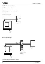
Страница 6: ...the voltage supply before starting connection work Active operation Ia 1 Passive operation Ip 1 1 Active or passive operation selectable with slide switch See 4 1 Indicating and adjustment elements Sensor Signal conditioning instrument VEGAMET Sensor Voltage supply Voltage supply 4 20 mA output 4 20 mA ...

Страница 7: ...enerally mounted outside hazardous areas Passive operation Ip 1 Electrical connection Intrinsically safe passive sensor e g pressure transmitter Signal and supply circuit sensor is powered 4 20 mA Ex area Ex area Active intrinsically safe signal circuit 4 20 mA VEGAPULS 81 E Ex 1 Active or passive operation selectable with slide switch See 4 1 Indicating and adjustment elements Voltage supply Volt...

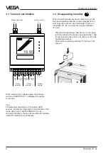
Страница 8: ...e terminals of the sensor input terminals 1 and 2 and loop the sensor line to the front out of the Ex separating chamber Push the Ex separating chamber to the front until snap in 3 3 Terminal coordination Relay 3 Rel 4 Relay 2 Relay 1 Relay module 2 Relay module 1 Voltage supply When switching on voltage supply the software version of VEGADIS 371 is displayed for approx 4 seconds Tipp For paramete...

Страница 9: ...rewdriver by a quarter turn and the cover 5 opens To protect the instrument against unauthorized adjustment the cover 5 of VEGADIS 371 can be sealed Insert the seal wire with closed cover in the top left corner through the hole of the lug Designation In practise it has proven to mark VEGADIS Informati on on the appropriate measurement loop and the unit of the indicated value help to avoid failures...

Страница 10: ...on conditions for Ex instruments VEGADIS 371 Ex Also note the type approval or the conformity certificate of VEGADIS 371 Ex Rotating switch 7 Stage 1 In menu stage 1 you find all necessary functions which are necessary for adjustment of the indicating instrument When you are in menu stage 1 the VEGA logo is shown non flashing Note When you want to activate the pump changeover function all relay ou...

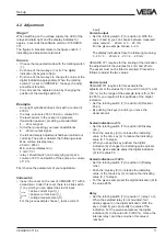
Страница 11: ...se Ia active current input Current output Set the rotating switch 7 to position A With the keys 3 and 4 you can choose between measured value output 4 20 mA or 0 20 mA For the given example choose 4 20 The display indications have the following meaning 0 20 0 20 mA 4 20 4 20 mA VEGADIS 371 requires for the scaling of the indication the adjustment of the volumes for 4 mA and 20 mA The vessel must n...

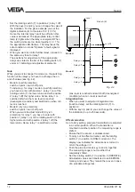
Страница 12: ... condition and switched on when min level is reached Mode B dry run protection switch on point switch off point When you want to adjust mode B dry run protection for relay 1 you have to enter with position 1 relay 1 on of the rotating switch 7 the higher value and with position 2 relay 1 off the lower value Hence relay 1 is switched on when Set up max level is reached and switch off deenergized co...

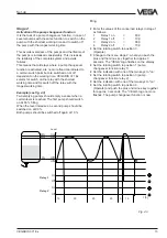
Страница 13: ...hen a certain level is reached The first pump should switch on at 80 filling When the level increases a second pump should be switched on at 90 Both pumps should be switched off again at 10 filling Enter the values of the concerned relays in stage 1 as follows 1 Relay 1 on 80 0 2 Relay 1 off 10 0 3 Relay 2 on 90 0 4 Relay 2 off 10 0 Set the rotating switch to position 0 Operate Change to the menu ...

Страница 14: ...on of a relay is activated the working times can be enquired positions of the rotating switch 2 4 6 8 The working times of the relays which are coordinated to the pump changeover function are saved every 8 hours in the EEPROM i e the data saved last remain even in case of power failure The working time is indicated in hours The max indication is 9999 hours over 1 year If this value is exceeded the...

Страница 15: ...d the two keys pushed Switch on the supply voltage The display indicates RES The instrument carries out a reset VEGADIS 371 has the following fatory setting Reset Default values Factory setting Menu stage 1 Relay switch on points 10 0 Relay switch off points 100 0 Display min 0 Display max 100 Decimal point 1 position Integration time 0 s Offset correction 0 μA Current output 4 20 mA Menu stage 2 ...

Страница 16: ...ce all adjusted values are reset to factory setting When the failure occurs again send the instrument to our repair department E014 Shortcircuit Relays deenergize safe condition current output 22 mA Sensor current 21 mA Check the terminals and the connection line to the sensor E015 Line break Relays deenergize safe condition current output 22 mA Sensor current 3 6 mA Check the terminals and the co...

Страница 17: ...VEGADIS 371 Ex 17 Notes ...

Страница 18: ...18 VEGADIS 371 Ex Notes ...

Страница 19: ...VEGADIS 371 Ex 19 Notes ...

Страница 20: ...ions of the sensors and processing systems correspond to the actual knowledge at the date of printing Technical data subject to alteration VEGA Grieshaber KG Am Hohenstein 113 D 77761 Schiltach Phone 0 78 36 50 0 Fax 0 78 36 50 201 e mail info de vega com 19893 EN 060426 ...

Отзывы: