14
VEGADIS 371 Ex
realised for both pumps (relay 1 and 2).
4.3 Mounting of the relay modules
Up to 2 relay modules with 2 output relays each can be
mounted in VEGADIS 371. The mounting should be
made by skilled staff. Ex-approved instruments must
not be modified afterwards. When you want to retrofit
VEGADIS 371 Ex, send the instrument to VEGA. With
two relay modules totally 4 output relays are available.
• Switch off voltage supply.
• Loosen the front of the housing of VEGADIS 371
with a coin or a screwdriver. On the lower side of
the housing there is a slot.
• Remove the front of the housing. You do not have to
loosen the connection cable of the digital indication
to mount the relay modules.
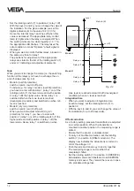
• Plug the first relay module carefully to module 1.
Note that the pins are not bent (see fig. 4.4).
• Fasten the relay module with a small screwdriver.
• A sticker is attached to the relay where the terminal
coordination is visible. Place this sticker to the
instrument housing in front of the appropriate
terminals.
• Connect the terminals of the relays.
• Switch the supply voltage on.
• Adjust the switch points so that you can use the
Set-up
Indication of the working times
When the pump changeover function of a relay is
activated, the working times can be enquired (positions
of the rotating switch 2, 4, 6, 8)
The working times of the relays which are coordinated
to the pump changeover function are saved every 8
hours in the EEPROM, i.e. the data saved last remain
even in case of power failure.
The working time is indicated in hours. The max.
indication is 9999 hours (over 1 year). If this value is
exceeded, the working time indication starts again at
0.
When you deactivate the pump changeover function of
a relay, the working time indication is set to 0 and
switched off.
When you carry out a reset, the pump changeover
function for all relays is deactivated and the working
time indication of all relays is reset to 0.
You can add or remove each relay individually to/from
the pump changeover function. Any combination is
possible.
The coordinated relays must all be operated in the
same mode (A/B):
Mode A
(overfill protection)
Switch on point < Switch off point
Switch on relay:
The relay with the shortest working time
switches on.
Switch off relay :
The relay with the longest working time
switches off.
Mode B
(dry run protection)
Switch on point > Switch off point
Switch on relay:
The relay with the shortest working time
switches on.
Switch off relay:
The relay with the longest working time
switches off.
Note
The cover is lockable to protect the instrument against
unauthorized adjustment.
Fig. 4.4
Содержание VEGADIS 371 Ex
Страница 1: ...8888 Operating Instruction VEGADIS 371 Ex VEGADIS 371 Ex 16 85 ...
Страница 17: ...VEGADIS 371 Ex 17 Notes ...
Страница 18: ...18 VEGADIS 371 Ex Notes ...
Страница 19: ...VEGADIS 371 Ex 19 Notes ...

