17
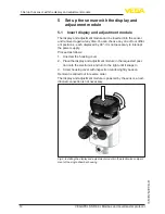
5 Set up the sensor with the display and adjustment module
VEGAPULS SR 68 • Modbus and Levelmaster protocol
47164-EN-140129
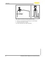
The following circumstances cause interfering reflections and can
influence the measurement:
•
High sockets
•
Vessel installations such as struts
•
Agitators
•
Buildup or welded joints on vessel walls
Note:
A false signal suppression detects, marks and saves these false sig
-
nals so that they are no longer taken into account for level measure-
ment.
This should be done with the low level so that all potential interfering
reflections can be detected.
Proceed as follows:
1. Select the menu item "
Additional settins
" with
[->]
and confirm
with
[OK]
. With
[->]
you have to select the menu item "
False
signal suppression
" and confirm with
[OK]
.
2. Confirm again with
[OK]
.
3. Confirm again with
[OK]
.
4. Confirm again with
[OK]
and enter the actual distance from the
sensor to the product surface.
5. All interfering signals in this section are detected by the sensor
and stored after confirming with
[OK]
.
Note:
Check the distance to the product surface, because if an incorrect
(too large) value is entered, the existing level will be saved as a false
echo. The filling level would then no longer be detectable in this area.
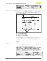
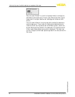
If a false signal suppression has already been created in the sensor,
the following menu window appears when selecting "
False signal
suppression
":
Additional adjustments -
False signal suppression


