15
5 Set up the sensor with the display and adjustment module
VEGAPULS SR 68 • Modbus and Levelmaster protocol
47164-EN-140129
1
2
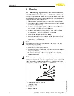
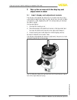
Fig. 10: Insertion of the display and adjustment module into the double chamber
housing
1 In the electronics compartment
2 In the connection compartment (with Ex-d-ia version not possible)
Note:
If you intend to retrofit the instrument with a display and adjustment
module for continuous measured value indication, a higher cover with
an inspection glass is required.
5.2 Parameter adjustment
1. Go via the display and adjustment module to the menu "
Setup
".
2. Select in the menu item "
Medium
" the medium of your applica-
tion, for example "
Powder/Dust
".
3. Select in the menu item "
Application
" the vessel, the application
and the vessel form, for example, silo.
4. Carry out the adjustment in the menu items "
Min. adjustment
" and
"
Max. adjustment
".
Set parameters


