background image

4

1 For your safety

MINITRAC 31 • Foundation Fieldbus

62076-EN-190704

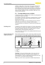
This measuring system uses gamma rays. Therefore take note of the 

instructions for radiation protection in chapter "

Product description

". 

Any work on the source container may only be carried out under the 

supervision of a qualified radiation protection officer.

1.5  EU conformity

The device fulfils the legal requirements of the applicable EU direc-

tives. By affixing the CE marking, we confirm the conformity of the 

instrument with these directives.
The EU conformity declaration can be found on our homepage.

Electromagnetic compatibility

Instruments with plastic housing are designed for use in an industrial 

environment. Nevertheless, electromagnetic interference from electri-

cal conductors and radiated emissions must be taken into account, 

as is usual with class A instruments according to EN 61326-1. If the 

instrument is used in a different environment, the electromagnetic 

compatibility to other instruments must be ensured by suitable meas-

ures.

1.6  NAMUR recommendations

NAMUR is the automation technology user association in the process 

industry in Germany. The published NAMUR recommendations are 

accepted as the standard in field instrumentation.
The device fulfils the requirements of the following NAMUR recom-

mendations:

• 

NE 21 – Electromagnetic compatibility of equipment

• 

NE 43 – Signal level for fault information from measuring transduc-

ers

• 

NE 53 – Compatibility of field devices and display/adjustment 

components

• 

NE 107 – Self-monitoring and diagnosis of field devices

For further information see www.namur.de.

1.7  Security concept, Bluetooth operation

Sensor adjustment via Bluetooth is based on a multi-stage security 

concept.

Authentication

When starting Bluetooth communication, an authentication is carried 

out between sensor and adjustment device by means of the sensor 

PIN. The sensor PIN is part of the respective sensor and must be 

entered in the adjustment device (smartphone/tablet). To increase 

adjustment convenience, this PIN is stored in the adjustment device. 

This process is secured via an algorithm acc. to standard SHA 256.

Protection against incorrect entries

In case of multiple incorrect PIN entries in the adjustment device, 

further entries are possible only after a certain amount of time has 

passed.

Содержание MINITRAC 31

Страница 1: ...Quick setup guide Radiometric sensor for density measurement MINITRAC 31 Foundation Fieldbus Document ID 62076...

Страница 2: ...necting to power supply 17 4 1 Preparing the connection 17 4 2 Connection Density mass flow rate measurement 19 4 3 Connection Level detection 22 5 Set up with the display and adjustment module 24 5 1...

Страница 3: ...with all prevailing regulations and directives The instrument must only be operated in a technically flawless and reliable condition The operator is responsi ble for the trouble free operation of the...

Страница 4: ...AMUR is the automation technology user association in the process industry in Germany The published NAMUR recommendations are accepted as the standard in field instrumentation The device fulfils the r...

Страница 5: ...low ing text is only available in the English language Installations in the US shall comply with the relevant requirements of the National Electrical Code ANSI NFPA 70 Installations in Canada shall co...

Страница 6: ...ry date HTML Order specific instrument features HTML Operating instructions and quick setup guide at the time of ship ment PDF Order specific sensor data for an electronics exchange XML Test certifica...

Страница 7: ...measurement 4 Mass flow measurement Further application possibilities are also the use as X ray alarm or real value correction If X ray alarm is selected the instrument detects radiation from exter na...

Страница 8: ...points are important for measurement with radiometric methods A handling permit is required for operation of a system using gamma rays This permit is issued by the respective government office or the...

Страница 9: ...radiation protection ordinance is complied with and for implementing all radiation protection measures Control areas are areas in which the local dose rate exceeds a certain value Only persons who und...

Страница 10: ...gh cleaning processes and on cooled or heated vessels Note Make sure that the degree of contamination specified in chapter Technical data meets the existing ambient conditions Note Make sure that duri...

Страница 11: ...mounting information for your measuring point You must follow the instructions in this Source Sizing document in addition to the following mounting instructions The following mounting information is...

Страница 12: ...urement A density and concentration measurement is possible on pipelines and vessels The accuracy of the measurement increases in propor tion to the radiated length L of medium This is particularly im...

Страница 13: ...L 3 Extension of the radiated length L by adding a tube angle piece as meas uring distance 4 Integrated lead cover as protection against ambient radiation the instru ment is hence shielded laterally...

Страница 14: ...Fig 6 Mass flow rate measurement 1 Flow meter 2 MINITRAC 31 Point level detection For level detection the sensor is generally mounted horizontally at the height of the requested limit level Make sure...

Страница 15: ...1 Horizontal mounting 2 Vertical mounting 3 Mounting horizontally at right angles to container Level measurement Residue detection The MINITRAC 31 can be used for residue detection e g in storage tan...

Страница 16: ...rom the heat source Make sure these measures are taken into account already in the plan ning stage If you want to carry out such measures later on contact our specialists to ensure that the accuracy o...

Страница 17: ...tle strip approx 1 cm 0 4 in of insulation from the ends of the individual wires 4 Insert the cable into the sensor through the cable entry 1 Fig 9 Connection steps 4 and 5 1 Locking of the terminal b...

Страница 18: ...nect the external ground terminal to potential equalisation 9 Tighten the compression nut of the cable entry gland The seal ring must completely encircle the cable 10 Screw the housing lid back on The...

Страница 19: ...transistor 6 Switching input floating 7 Transistor output 8 Interface for sensor sensor communication MGC 9 Simulation switch 1 simulation on 10 Setting the bus address for sensor sensor communicatio...

Страница 20: ...PE 5 6 22 11 12 21 22 19 20 18 17 14 13 16 15 12 Fig 12 Electronics and connection compartment Ex d with instruments with intrinsically safe signal output 1 Voltage supply 2 Relay output 3 Signal inp...

Страница 21: ...with instruments with intrinsically safe signal output 1 Terminals for intrinsically safe signal output FF bus 2 Contact pins for the display and adjustment module or interface adapter 3 Terminals for...

Страница 22: ...n MGC 9 Simulation switch 1 simulation on 10 Setting the bus address for sensor sensor communication MGC 3 5 6 7 8 2 1 Fig 15 Adjustment and connection compartment with non Ex instruments and instrume...

Страница 23: ...output 7 Interface for sensor sensor communication MGC 8 Simulation switch 1 simulation on 9 Setting the bus address for sensor sensor communication MGC 4 5 6 7 8 2 3 4 1 2 1 Fig 17 Adjustment and con...

Страница 24: ...isplay and adjustment module onto the electronics and turn it to the right until it snaps in 4 Screw housing lid with inspection window tightly back on Disassembly is carried out in reverse order The...

Страница 25: ...setup or after an instrument reset the instrument starts with preset standard values These value are not suitable for your ap plication and must be replaced by real values 5 2 1 Setup Enter here the r...

Страница 26: ...ensor First of all select the unit of the inside diameter Enter in the menu window Inside diameter the inside diamter of the tube for example in cm If the tube is not radiated with 90 then you have to...

Страница 27: ...process conditions or the voltage supply Electromechanical data version IP 66 IP 67 Cable entry M20 x 1 5 2 x cable gland M20 x 1 5 cable 6 12 mm 4 x blind plug M20 x 1 5 Included 1 x cable gland M20...

Страница 28: ...of delivery application practical use and operat ing conditions of the sensors and processing systems correspond to the information available at the time of printing Subject to change without prior n...

Отзывы: