background image

Current Utilization: 

Current channel utilization in % over the duration of the test. It measures the percentage of time that

the RF channel is detected as “busy” and that the radio could not initiate communication. The channel could be detected

as “busy” because of WiFi transmissions by APs on the channel or non-WiFi interference on the same frequency as the

channel under test.

Overlapping APs:

 Number of Access Points/SSIDs whose spectrum overlap on the channel.

Max Overlap

: Signal level in dBm of the strongest overlapping AP. Displays “N/A” if there are no overlapping APs on the

channel.

The 

Details 

function key provides these additional measurements:

Min Freq: 

Channel’s lower frequency in GHz. WiFi Channels are 20 MHz wide.

Center Freq:

 Channel’s center frequency in GHz. WiFi Channels are 20 MHz wide.

Max Freq:

 Channel’s upper frequency in GHz. WiFi Channels are 20 MHz wide.

List of co-channel APs:

 List of SSIDs of the APs located on the channel and their signal level in dBm.

List of Overlapping APs: 

List of SSIDs of the APs located on overlapping channels and their signal level in dBm.

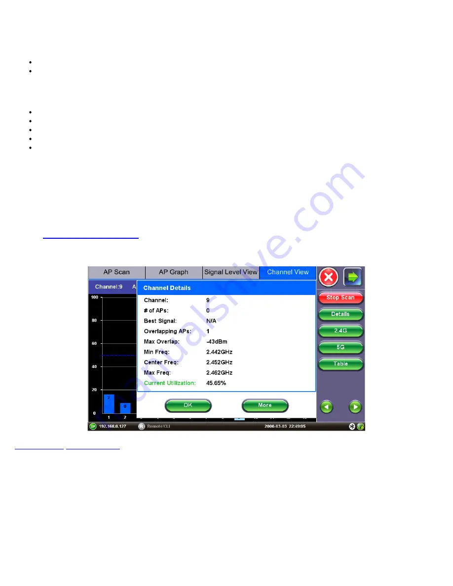
7.5.4 Channel View Details Window

Selecting a Channel from the Channel View Graph or Table and pressing the 

Details

 function key opens up a pop-up window

with additional details. 

Fields displayed on the details window may or may not be present depending on the information being advertised by the AP. 

Press 

OK

 to close the Details window and return to previous screen. 

Press 

More 

to view the next page of the Details window.

Refer to 

Channel View Measurements

 for a description of measurements presented in the 

Details

 window.

Channel View Details screen

Go back to top


Go back to TOC

WiFiAirExpertSeries_eManual_D07-00-120P_Rev A00

Содержание MTTplus-900

Страница 1: ...WiFiAirExpertSeries_eManual_D07 00 120P_Rev A00...

Страница 2: ...tennas 4 2 WX150 Platform Overview 4 2 2 Test Port Interfaces and Antennas 4 2 2 1 Connector Panel 4 2 2 2 WX150 Antennas 4 2 3 Quick Side Buttons 4 3 Home Menu and Navigation 4 3 1 Screen Icons 4 3 2...

Страница 3: ...Function Keys 7 1 3 AP Scan Fields and Measurements 7 1 4 AP Scan Details Window 7 1 5 AP Scan Warning Conditions 7 2 AP Locate Function 7 3 AP Graph 7 3 1 AP Graph Navigation 7 3 2 AP Graph Function...

Страница 4: ...alyzer Specifications 9 2 Spectrum Analyzer Default View 9 2 1 Spectrum Analyzer Default View Function Keys 9 2 2 Using the Marker Function 9 3 Levels Graph 9 3 1 Using the Show AP Function 9 4 Densit...

Страница 5: ...1 0 V Perf 11 1 V Perf Configuration Settings 11 2 V Perf Test Results 11 2 1 V Perf Summary Results 11 2 2 Data Rate vs Phy Rate 11 2 3 V Perf Graph Results 11 2 4 V Perf Details Results 12 0 Etherne...

Страница 6: ...be B 3 1 Running a Manual V Perf Test to a V Probe B 3 2 Running a Quick V Perf Test to a V Probe B 4 V Probe Configuration B 4 1 V Probe Configuration from a PC Web Browser B 4 2 V Probe IP Configura...

Страница 7: ...ed electronically or otherwise without written permission from VeEX Inc This device uses software either developed by VeEX Inc or licensed by VeEX Inc from third parties The software is confidential a...

Страница 8: ...ciated WiFi Clients present in the network Locate rogue APs and clients with directional antenna One button Auto Test evaluates the health of the WiFi network with analysis of security coverage interf...

Страница 9: ...nd protection circuitry sealed in its plastic container that shall not be disassembled or serviced The test set unit s battery pack is also fitted with a safety connector to prevent accidental short c...

Страница 10: ...form all work at a workplace that is protected against electrostatic build up and discharging Never touch any exposed contacts printed circuit boards or electronic components Always store test modules...

Страница 11: ...r panel A Ethernet RJ45 10 100 1000Base T Optional interface for 10 100 1000Base T Ethernet test For Ethernet interface operation refer to Ethernet Setup B Ethernet SFP 1000Base X Optional interface f...

Страница 12: ...back to TOC WiFi Directional Antenna Directional Antenna For the WiFi AP or Client Locate function it is possible to use a directional antenna connected to the WiFi connector from the connector panel...

Страница 13: ...o TOC 4 2 2 Test Port Interfaces and Antennas 4 2 2 1 Connector Panel The connector panel located at the top of the unit comprises the following test ports WX150 Connector Panel Note Ethernet RJ45 10...

Страница 14: ...esults Note Button functions vary depending on the product Push in Reveal function keys such as starting stopping tests Left key Scrolls up and down through table results Right key Scroll left and rig...

Страница 15: ...lays if no Client is detected or Client Scan test has not been started D Connection This icon displays the connection status to the AP From the Home menu tap on this icon to open up the IP Connect men...

Страница 16: ...results table and locate function see Client Scan menu E Spectrum Analyzer Open the Spectrum Analyzer menu to access the Spectrum Analyzer results Note that this function requires hardware option See...

Страница 17: ...testing functions Ping Trace Route ARPWiz see Ethernet IP Connect C V Perf Open the V Perf menu to access the V Perf throughput performance testing function Note that prior IP connection must be estab...

Страница 18: ...ese channels it will be flagged as an error In World mode the unit accepts all channels Active Probe From the drop down menu select ON or OFF If Active Probe setting is ON the Air Expert transmits pro...

Страница 19: ...ial and Business Location Label lists comes with 14 pre populated location labels reflecting the most common places to run the site survey Each can be further edited or overwritten using the magnifyin...

Страница 20: ...the drop down menu select Enable or Disable Enable The values in the threshold setting will be used to display pass warning and fail results in the Coverage Auto test and AP scan menus Disable SNR wi...

Страница 21: ...arning and Fail results that reveal network quality Because Pass Warning and Fail results are determined from threshold values changing threshold values will alter test results How to Configure Thresh...

Страница 22: ...red Adjacent Channel Interference Compares the number of APs on a channel adjacent to the AP under test Returns Pass Warning or Fail result Applicable Screens Interference Auto test Note Only APs whos...

Страница 23: ...nnels are used on the network It also detects hidden networks and encryption status Coverage Check During the Coverage Check see Coverage Check Auto Test the Air Expert identifies APs and Channels wit...

Страница 24: ...2 Press the red X to close the AP filter selection and return to the Setup menu 3 Tap on the check box next to AP Filter to enable it Note that the AP filter list is first populated by running a regul...

Страница 25: ...test see Auto Channel Selection Go back to top Go back to TOC 6 2 2 Auto Test Results Navigation For each test category one of the following icons is displayed If no icon is displayed the test was dis...

Страница 26: ...asionally network managers prefer to hide the AP s SSID for security reasons In that instance a blank SSID name or hidden is displayed instead The Hidden AP test displays a warning for all Hidden APs...

Страница 27: ...Level Threshold value are examined as possible sources of interference for this test Other APs sharing on the same overlapping or adjacent channels but with a signal level lower than the threshold val...

Страница 28: ...AP it will be ignored during the test Note If AP Filter is enabled see AP Filter Setup only APs selected in the filter list are taken into account for these tests Go back to top Go back to TOC 6 2 7 C...

Страница 29: ...ell as current utilization and noise levels on all the channels in order to recommend the best channel for a new AP deployment In the 2 4 GHz frequency band the ACS algorithm recommends a channel betw...

Страница 30: ...over time Go back to top Go back to TOC WiFiAirExpertSeries_eManual_D07 00 120P_Rev A00...

Страница 31: ...re than 2 minutes are aged out of the table AP Scan Table Go back to top Go back to TOC 7 1 1 AP Scan Table Navigation Discovered AP scan measurements are displayed in a table format Common table navi...

Страница 32: ...electing Apply the AP Scan table displays only entries corresponding to the input Press the Clear Filter function key to clear existing filters and display all AP Scan entries BSSID will be filtered b...

Страница 33: ...all AP Scan entries Go back to top Go back to TOC 7 1 3 AP Scan Fields and Measurements The following measurements are displayed in the AP Scan Table results as well as the AP Details window Results...

Страница 34: ...t this information If this information is not reported by the AP the field displays N A The Details function key provides these additional measurements Vendor AP s manufacturer name If this informatio...

Страница 35: ...nu and the current measured noise level is above the green level threshold SNR Level warning If the Signal to Noise Level Threshold is enabled in the Measurement Setup menu and the current measured SN...

Страница 36: ...ternal antennas For antenna selection refer to WiFi Setup AP Locate Function SSID Service Set Identifier advertised by the Access Point The SSID is the logical name used to identify the network SSID i...

Страница 37: ...ted in blue Graph Pane Navigation Use the Up and Down arrow keys to scroll through Access Points detected on the same channel Use the Left and Right arrow keys to scroll through Access Points on adjac...

Страница 38: ...al Level View From the AP Scan Table select an SSID from the list and select the Track Level function key to start tracking the Signal Noise level and SNR for the SSID selected The Track Level functio...

Страница 39: ...OK to select the labels or More for additional labels The Track Level function starts recording the Signal Noise level and SNR values for the SSID under test A measurement is made every second Signal...

Страница 40: ...ction keys displayed while Signal Level tracking is running Start Scan Starts a new AP network scan Warning Starting the network AP will stop the current Signal Level tracking in progress Stop Stops i...

Страница 41: ...ed in the Setup menu see Signal Level Tracking with Location Label Last Rx frame counter The Signal level tracking measurement is based on the Signal level measured on frames received from the SSID un...

Страница 42: ...tilization Results are updated while the network scan is running Channel Utilization measures the percentage of time that the RF channel is detected as busy and that the radio could not initiate commu...

Страница 43: ...o additional functions The functions are accessed through the right side function keys Channel Table selection 7 5 2 Channel View Function Keys The function keys are located on the right hand side of...

Страница 44: ...WiFi interference on the same frequency as the channel under test The x axis displays the channel number the y axis displays utilization in The number included in each bar graph displays the number of...

Страница 45: ...cy in GHz WiFi Channels are 20 MHz wide Max Freq Channel s upper frequency in GHz WiFi Channels are 20 MHz wide List of co channel APs List of SSIDs of the APs located on the channel and their signal...

Страница 46: ...Table Go back to top Go back to TOC 8 1 1 Client Scan Table Navigation Refer to section AP Scan Table Navigation for information on how to navigate sort filter and select table features Go back to to...

Страница 47: ...interface If the WiFi client is not associated to any network this field displays not associated Max AP Rate Maximum Phy rate in Mbps supported by the AP to which the client is associated If the clien...

Страница 48: ...the Client Scan Table and pressing Details opens up a pop up window with additional details Fields displayed on the details window may or may not be present depending on the information being adverti...

Страница 49: ...e function key to open up the Locate function for the client selected The Locate function is used to track the physical location of the client It measures the signal level of the traffic received from...

Страница 50: ...Hz and 5 150 to 5 850 GHz Amplitude Range 100 to 6 5 dBm Amplitude Resolution 0 5 dBm Resolution Bandwidth 214 286 KHz in 2 4 GHz band 464 286 KHz in 5 GHz band Sweep Time 2 4 GHz 507 msec low 5 GHz 1...

Страница 51: ...Waterfall Switches the screen view to display the Waterfall view see Waterfall Graph Restart Clears all previous measurements and restarts the spectrum measurement Marker ON or OFF Toggle function key...

Страница 52: ...w The y axis displays the signal s strength in dBm from 100 dBm to 10 dBm By default the current yellow average green and maximum blue signal levels are displayed simultaneously Use the checkboxes Cur...

Страница 53: ...ion with spectrum information which facilitates identifying WiFi vs non WiFi interference sources Spectrum Analyzer Levels Graph with AP overlay Go back to top Go back to TOC 9 4 Density Graph The Den...

Страница 54: ...n the spectrum graph Use the Signature function Using the Signature Function to identify interferers signatures Spectrum Density Graph Go back to top Go back to TOC 9 4 1 Using the Signature Function...

Страница 55: ...making the selection as it only reflects the strength i e proximity to the interference source For descriptions of common interference sources refer to Common WiFi Interferers The following figure sho...

Страница 56: ...requency Note that 802 11ac devices have the same shape but can only operate in the 5 GHz frequency band 802 11n 40 MHz Signature BPSK QPSK 802 11b g 802 11b g devices using older technology of BPSK Q...

Страница 57: ...pike like interference in the 2 4 GHz frequency band AV transmitter Signature Bluetooth Bluetooth devices are frequency hopping across the 2 4 GHz frequency band Their signature appears as a series of...

Страница 58: ...ill transmit over a single frequency with a width of about 2 MHz but use a new frequency at each use Generally cordless phones are disruptive because they emit with high power Cordless Phone Signature...

Страница 59: ...only operates in the 2 4 GHz frequency band and uses only 20 MHz channel width ERP OFDM 802 11g Wireless Audio Wireless audio systems transmit audio to remote speakers using the 2 4 GHz frequency ban...

Страница 60: ...ngth The waterfall view is particularly useful to detect intermittent interference or interference where frequency changes over time hopping The x axis displays the WiFi channel number In the 2 4 GHz...

Страница 61: ...e high signal level Use the Marker function Using the Marker Function to view the level values for the frequency WiFi Spectrum Analyzer Waterfall View Go back to top Go back to TOC WiFiAirExpertSeries...

Страница 62: ...nction Keys The function keys are located on the right hand side of the screen and allow access to advanced functions Different function keys are available depending on whether the network scan is run...

Страница 63: ...Occasionally network managers prefer to hide the AP s SSID for security reasons In that case a blank SSID name or hidden are displayed instead BSSID Basic Service Set Identifier for the AP The BSSID i...

Страница 64: ...le icons The following statuses can be displayed This icon indicates that the connection credentials for the AP are saved to a profile This icon indicates that the connection credentials for the AP ar...

Страница 65: ...P s SSID for security reasons In that case a blank SSID name or hidden are displayed instead BSSID Basic Service Set Identifier for the AP The BSSID is a 48 bit unique MAC address of the AP s network...

Страница 66: ...tion on cause of failure Failed AP Connection Details Additional information in the Connection Status page provides details on causes of the failed requests In the example above failure is due to the...

Страница 67: ...or Disable If set to enable Gateway and DNS fields become available Gateway Off or On IPv4 address of the network gateway DNS Off Primary or Primary Secondary If set to Primary or Primary Secondary a...

Страница 68: ...address of the Primary DNS server DNS2 Indicates the IP address of the Secondary DNS server Go back to top Go back to TOC 10 5 Ping Ping is a popular computer network tool used to test whether a parti...

Страница 69: ...Result tab and starts the Ping test The following results are displayed for the Ping test Ping Test Results Ping status In Progress Finished Destination unreachable or Fail Destination Indicates the d...

Страница 70: ...Out Enter the maximum time allowed between an ICMP echo and response at each hop Max Hop Enter the maximum number of network devices the packet is allowed to transit Once the parameters are configure...

Страница 71: ...ng parameters can be setup for the ARPWiz test ARPWiz Setup Profile Drop down selections are Default Delete Save Save As Begin IP Set the start address for the desired IP range using the numeric keypa...

Страница 72: ...ms Time for ARP response message MAC Address MAC Hardware address of the device responding to ARP message Note If there is no response from a particular IP address it is omitted from the table Go back...

Страница 73: ...that validates whether TCP UDP parameters in the network are set up correctly Test traffic is generated between a unit acting as a server and a unit acting as a client A unit acting as a server shoul...

Страница 74: ...ns that can tolerate frame loss such as VoIP Transfer Direction From the drop down menu select Client to Server or Server to Client In the Client to Server transfer direction test data is transferred...

Страница 75: ...e used to display pass or fail results in V Perf Throughput test results If V Perf Throughput Threshold setting is Disabled V Perf throughput measurements won t be evaluated against Pass Fail threshol...

Страница 76: ...of the test this field displays the average value of data throughput UDP or TCP in Mbps over the entire duration of the test In addition to the data throughput in Mbps the value is also displayed as...

Страница 77: ...graph is graduated from 0 to 100 in 10 increments 0 represents a data rate of 0 Mbps and 100 represents the Max Phy rate advertised by the AP Depending on the APs capabilities this value will vary V P...

Страница 78: ...ring achieved TCP or UDP data rates to the WiFi Physical Layer rate the following considerations should be taken into account Achieved Data rate vs Max Phy rate The Maximum Phy Rate advertised by the...

Страница 79: ...ate are expected to be around 60 to 65 of the Phy rate due to IP and TCP UDP protocol overhead and WiFi physical layer and protocol layer overhead In addition when running iPerf3 on a server the serve...

Страница 80: ...displays an error message In case of test failure verify if the server s IP address and port number configured in Setup see V Perf Configuration Settings are accurate Also make sure that the V Perf s...

Страница 81: ...in UDP Server to Client Mode download V Perf Throughput Loss Graph X axis Time in HH MM SS format Y axis Received Packet Loss updated each second 11 2 4 V Perf Details Results The V Perf Details resul...

Страница 82: ...ssion rate depends on the AP and Client capabilities as well as the RF environment Refer to Data Rate vs Phy Rate for details The WiFi Air Expert series Maximum Phy Rate is 1299 Mbps Phy Rx bit Rate D...

Страница 83: ...ct the test mode The module can be configured for WiFi utilization Ethernet Copper port 10 100 1000T or Ethernet Fiber port 1000X 100FX utilization Auto Negotiation On or Off Matches the test set s ne...

Страница 84: ...Connect menu The Ethernet IP Connect functions work similarly to the WiFi IP Connect functions Refer to the following sections for more information on IP Connect functions Network Configuration Networ...

Страница 85: ...f The Ethernet V Perf function works in the same way as the WiFi V Perf function For more information on the V Perf menu refer to V Perf menu Go back to top Go back to TOC WiFiAirExpertSeries_eManual_...

Страница 86: ...ink is DOWN Pair Termination Indicates properly terminated pair Indicates an open pair Indicates improper pair termination short high crosstalk or anomalous coupling Cable Length estimation of properl...

Страница 87: ...Blinking in Progress Go back to top Go back to TOC WiFiAirExpertSeries_eManual_D07 00 120P_Rev A00...

Страница 88: ...y the customer along with proof of purchase within thirty 30 days of the request by the customer freight prepaid Additionally during the warranty period VeEX Inc will provide without charge to the cus...

Страница 89: ...Product Specifications The most recent product specifications can be downloaded from the WX150 product page of the VeEX website Go back to top Go back to TOC WiFiAirExpertSeries_eManual_D07 00 120P_Re...

Страница 90: ...f European Union and European Free Trade Association EFTA EN61010 1 Click here for CE Declaration of Conformity relating to VeEX products What is RoHS RoHS is the acronym for Restriction of Hazardous...

Страница 91: ...wide distribution channel provides uncompromised product support Visit us online at www veexinc com for latest updates and additional documentation VeEX Incorporated 2827 Lakeview Court Fremont CA 945...

Страница 92: ...Access Points Channel 36 is the first channel in the spectrum ranging from 5 170 to 5 190 GHz and centered at 5 180 GHz The 5 GHz band is further sub divided into four ranges UNII 1 UNII 2 UNII 2 ext...

Страница 93: ...est status LED OFF V Probe is turned off LED Solid Green V Probe is on and fully operational LED Quickly Blinking Green If the V Probe s LED is quickly blinking 200 ms interval it indicates that a V P...

Страница 94: ...Base T interface or WiFi air interface and use V Probe Discovery function B 3 Running V Perf Tests to a V Probe B 3 1 Running a Manual V Perf Test to a V Probe Note Before running V Perf make sure tha...

Страница 95: ...nged tap on the magnifying glass icon If any V Probe IP settings need to be modified tap on the world icon to open the V Probe web browser Alternatively type the V Probe IP address into a PC web brows...

Страница 96: ...assigned DHCP IP address 1 Connect the test set to the Access Point under test from the AP Scan table accessed from the AP Scan icon on the home menu Refer to Connect AP for more information on conne...

Страница 97: ...way DNS then click Apply 5 Click Reboot when prompted to do so Connect to V Probe with the new IP address via the test set or web browser B 4 2 V Probe IP Configuration 1 From the V Probe home page se...

Страница 98: ...ow to setup registration Contact VeEX customer support for information about XMPP server configuration B 6 System Tools B 6 1 Reboot Click on System Tools Reboot Click Reboot when prompted to reboot t...

Страница 99: ...mode Factory Reset from USB This procedure can be used when the V Probe cannot be discovered via V Probe Discovery and its IP address is unknown B 7 Safe Shut Down Safely shutting down the V Probe is...

Отзывы: