background image

6


Setup

Introduction

This section describes how to program the TLS-450PLUS for In-Station Diagnostics using the front panel 

graphical user interface (GUI). The procedures in this manual follow standard TLS-450PLUS console setup 

programming methods. All ISD-related equipment must be installed at the site and connected to the TLS console 

prior to beginning the setups covered in this section. As with all TLS connections, you cannot change sensor 

wiring or module slots after programming or the system will not recognize the correct data. Reference the section 

entitled “Probe and Sensor Field Wiring” in the TLS-450PLUS Site Prep and Install manual (P/N 577014-073) for 

rewiring precautions.

Date/Time Setup

This screen lets you enter the current date and time for the console. It is especially important to update the time 

when setting up the console.
It is very important when entering the date and time, you do not set it into the future. A future date and time will 

affect the proper posting of ISD reports, even after making any corrections. Should this situation occur, contact 

Veeder-Root Tech Support.

Prior to setting Date and Time on initial startup, you must remove the protective tab 

underneath the backup battery. This tab is yellow with an X printed on it. The battery can be 

found on the PC board inside the left front door of the console. Date and Time will not be 

entered correctly if this yellow tab is not removed.

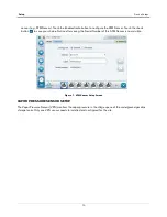
1. Touch Menu>Setup>Date and Time (see Figure 2).

Figure  2.  Date and Time Setup Screen

2. Ensure the Current Date and Current Time field entries are correct.

3. Ensure the Time Zone entry is 

(UTC-07) US/Pacific

 as shown in Figure 2.

4. Touch the check button 

 to save your choices.

Содержание TLS-450PLUS

Страница 1: ...Manual No 577014 484 Revision B Install Setup Operation Manual In Station Diagnostics ISD TLS 450PLUS Consoles for Veeder Root Polisher and Healy CAS...

Страница 2: ...roduct at no charge to the customer Customer Service will work with production facility to have the replacement product shipped as soon as possible CUSTOMER S PREFERRED CARRIER 1 It is the customer s...

Страница 3: ...site access during Customer s regular working hours to work on the equipment Veeder Root has no obligation to monitor federal state or local laws or modify the equipment based on developments or chan...

Страница 4: ...t that this product shall be free from defects in material and workmanship and is compliant with all applicable performance standards and specifications for which it has been certified for a period of...

Страница 5: ...25 Vapor Management 28 Processor 28 Automatic Events Setup Shutdown Requirements ISD 30 Pump Mode Setups 30 Automatic Events Pump Mode TLS Pump Control 30 Pump Mode TLS Pump Control 30 Automatic Event...

Страница 6: ...Time Setup Screen 6 Figure 3 Accessing Device Setup 7 Figure 4 Accessing Air Flow Meter Setup Screen 7 Figure 5 Air Flow Meter Setup Screen 8 Figure 6 Accessing ATM Pressure Sensor Setup Screen 9 Figu...

Страница 7: ...lay s 32 Figure 48 Example Device Task Pump Sense No Dispenser relay s 33 Figure 49 Example Device Task Pump Sense Line Out No Dispenser relay s 33 Figure 50 Example Device Task Pump Sense With Dispen...

Страница 8: ...on 68 Figure 98 Connect Laptop to an Available RS 232 Comm Port 69 Figure 99 TLS 450PLUS RS 232 Connector Pin Outs 69 Figure 100 Example Serial Port Setup Screen 70 Figure 101 Example Serial Port 3 Se...

Страница 9: ...ons shipped with module Setup ISD shutdown alarms in Automatic Events section of this manual c ISD requires dispenser transactions to be collected Refer to TLS Consoles Point of Sale POS Application G...

Страница 10: ...rements Installer Certification6 ATG Technician Certification7 VR Vapor Products Certification8 TLS 450PLUS EVR for CA Certification Install1 ISD X X X X Install PMC X X X X Install CCVP X X X X Insta...

Страница 11: ...d is supplied to the device A potential shock hazard exists TURN POWER OFF Live power to a device creates a potential shock hazard Turn Off power to the device and associated accesso ries when servici...

Страница 12: ...l Dispenser Control MAG Probes STP STP MAG Probe MAG Probe TANK 2 TANK 3 To I O Module 937 24 eps STP Control Dispenser Fuel Meter Events Dispenser Fuel Meter Events Regulator Port RS 232 Vapor Pressu...

Страница 13: ...to shutdown on required ISD Site Hose alarms Hoses may also be shutdown using dispenser relays ISD shutdown requirements is accomplished using Automatic Events Setup Refer to Table 3 for required ISD...

Страница 14: ...e and time for the console It is especially important to update the time when setting up the console It is very important when entering the date and time you do not set it into the future A future dat...

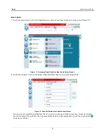
Страница 15: ...TLS 450PLUS i e Air Flow Meter Atmospheric Pressure Sensor Vapor Pressure Sensor and Vapor Valve AIR FLOW METER SETUP 1 Touch the Devices selection Figure 3 Figure 3 Accessing Device Setup 2 Touch th...

Страница 16: ...refers to its Dispenser FP location e g AFM FP1 2 then touch the Enabled radio button to configure the device Touch the button to save your choices Figure 5 Air Flow Meter Setup Screen 4 On the devic...

Страница 17: ...or Polisher or a PMC Setup Fail will occur NOTE if more than one ATM Pressure Sensor is installed only one ATM Pressure Sensor needs to be configured 1 Touch ATM Pressure Sensor in the Devices list Fi...

Страница 18: ...e your choice Notice after saving the Serial Number of this ATM Sensor is now visible Figure 7 ATM Sensor Setup Screen VAPOR PRESSURE SENSOR SETUP The Vapor Pressure Sensor VPS monitors the vapor pres...

Страница 19: ...Pressure Sensor Setup Screen 2 Touch the Address drop down box and select the address of the VPS sensor Touch the Label field and enter the label text for the sensor on the keypad then touch the gree...

Страница 20: ...xample Vapor Valve Setup Screen 2 Touch the Address drop down box and select the address of the Vapor Valve Touch the Label field and enter the label text for the Vapor Valve on the keypad e g Vapor V...

Страница 21: ...Appendix A for the vapor recovery system installed at your facility e g Single or Multi Hose Dispensers and record in those sheets all the unique information from sensors hose positions prior to begin...

Страница 22: ...d to begin using the last 24 hours of data Select the Vapor Pressure Sensor configured in the Pressure Sensor drop down box and touch the check button to save your choice VAPOR COLLECTION SETUP Go to...

Страница 23: ...e Estimated ORVRS EXPECTED message is posted to the Miscellaneous Event Log then set to Enabled Nozzle Type VST default This field is only available when the EVR Type is set to Balance Choices are VST...

Страница 24: ...s Setup Screens 2 Touch Hose Labels to access the Vapor Collection Hose Labels setup screen Figure 18 Figure 18 Vapor Collection Hose Labels Setup Screen You can select a default hose label from this...

Страница 25: ...Vapor Collection setup screen Figure 19 Touch Hose Settings to access the Vapor Collection Hose Settings setup screen Figure 20 Figure 19 Accessing Vapor Collection Hose Settings Setup Screen Figure 2...

Страница 26: ...tings Setup Example 3 Touch the drop down arrow in the Label field and select the Hose Label from the list see Figure 22 Figure 22 Vapor Collection Hose Settings Setup Example 4 Enter the FP Label num...

Страница 27: ...ttings Setup Example 5 Touch the drop down arrow in the Air Flow Meter field and select the AFM associated with this hose see Figure 24 Figure 24 Vapor Collection Hose Settings Setup Example 6 Touch t...

Страница 28: ...r all appropriate hoses by selecting the hose number icons on the bottom selection ribbon After saving an edit made for a hose in Hose Setup a pop up message will show and advise that the action will...

Страница 29: ...n Hose Mapping Setup Screen Figure 28 Vapor Collection Hose Mapping Setup Screen 2 Assisted mapping is easier on a site with previous events recorded on all fuel meters However we recommend that you s...

Страница 30: ...bel of Blend 3 There are two straight grades and two blended grades Figure 30 Example Dispenser Fuel Position 1 4 Begin the mapping process by dispensing a 0 25 to 0 5 gallons of the Straight Grade 87...

Страница 31: ...tch the FP Label Fuel Position number located on the dispenser Figure 31 Example First Meter Mapped for Hose 1 Unleaded Product 5 Next we will map the Straight Grade 93 by dispensing 0 25 to 0 5 gallo...

Страница 32: ...ave to repeat the dispense several times if Fueling Position logical or Fuel Meter does not display after waiting 30 seconds Check mapping carefully if you repeat dispenses 7 Next dispense 0 5 to 1 0...

Страница 33: ...on correct Is Air Flow Meter assignment correct Are the expected number of fuel meters assigned to a hose After completing hose mapping ensure that all hoses are locked see Figure 36 Figure 36 Example...

Страница 34: ...Setup Vapor Recovery Setup Figure 37 Example Missing Meter Map for Hose 3 1 To correct the hose 3 map manually select h 3 Blend3 to be edited see Figure 38 Figure 38 Example Hose 3 Selected for Editi...

Страница 35: ...hose 3 edit screen see Figure 39 and Figure 40 Figure 39 Example Selecting Hose 3 for Editing Figure 40 Hose 3 Edit Screen 2 Make the edit and touch the check button to save the screen Figure 41 Ente...

Страница 36: ...Reset Hose Map and Hose Settings option in Actions to default values to clear the entire Hose Mapping and Hose Setting screens Then proceed to create all the Hoses in Hose Settings and re map all the...

Страница 37: ...isher see Figure 44 Figure 44 Vapor Management Processor Setup Screen Page 1 3 Notice the Vapor Valve field self populates when there is a Vapor Valve configured as in this example Figure 45 Vapor Man...

Страница 38: ...SETUPS These steps are required for ISD Shutdown as per pump mode Available Pump Modes in Setup Pumps and Lines Pumps Setup Automatic Events Pump Mode TLS Pump Control Pump is controlled locally by t...

Страница 39: ...e gasoline Pump s to the Line b Via Setup Automatic Events Device Tasks Add a task for required ISD Site Alarms California Air Resources Board CARB requires that gasoline dispensing be shutdown for sp...

Страница 40: ...p Pumps and Lines Pumps Pump Sense The console senses if the pump is active when a pump request signal is sent to turn on off the pump this signal also acts as a tank active signal to the console PUMP...

Страница 41: ...ce to the Gasoline Line ii Select each required ISD Site Alarm as a Trigger iii Hose Site Shutdown Option Select the Hose Alarms for each Gasoline Hose as a Trigger Figure 48 Example Device Task Pump...

Страница 42: ...o Standard b Via Setup Automatic Events Device Tasks Add a task for each Dispenser Relay i Set the Device to the Relay ii Set each required Hose Alarm for the appropriate Gasoline Hose s as a Trigger...

Страница 43: ...e ii Assign the appropriate gasoline Pump s to the Line b Via Setup Automatic Events Device Tasks Add a task for required ISD Site Alarms California Air Resources Board CARB requires that gasoline dis...

Страница 44: ...spenser Relay Shutdown option For each Dispenser Relay a Via Setup Devices Relay i Configure Enable Relay ii Set the Type to Standard b Via Setup Automatic Events Device Tasks Add a task for each Disp...

Страница 45: ...up for the California Air Resources Board CARB can be generated This is the same as EVR ISD setup printout format that can be created with the TLS 350 console The CARB EVR ISD Printout 1 Via Menu Setu...

Страница 46: ...38 Setup Single CARB EVR ISD Setup Printout Figure 55 Example EVR ISD Setup Printout...

Страница 47: ...eens AIR FLOW METER OVERVIEW 1 Touch Menu Diagnostics Air Flow Meter Overview to display the Air Flow Meter Overview screen see Figure 57 Figure 56 Accessing the Air Flow Meter Overview Screen Figure...

Страница 48: ...ion for the selected Air Flow Meter Touch the scroll down arrow to view the rest of the Air Flow Meter data tables see Figure 58 Figure 58 Air Flow Meter Overview Screen Page 2 2 Touching Actions Help...

Страница 49: ...OVERVIEW VEEDER ROOT POLISHER ONLY 1 Touch Menu Diagnostics Atmospheric Sensor Overview to display the Atmospheric Sensor Overview screen see Figure 60 Figure 59 Accessing the Atmospheric Sensor Over...

Страница 50: ...ta tables see Figure 61 Figure 61 Atmospheric Sensor Overview Screen Page 2 3 Touching Actions Help opens the Online Help to view descriptive information about the data in the tables for this device V...

Страница 51: ...ay status information for the selected Vapor Pressure Sensor Touch the scroll down arrow to view the rest of the Vapor Pressure Sensor data tables see Figure 64 Figure 64 Vapor Pressure Sensor Overvie...

Страница 52: ...view to display the Vapor Valve overview screen see Figure 66 Figure 65 Accessing the Vapor Valve Overview Screen Figure 66 Vapor Valve Overview Screen Page 1 2 The four tables in this screen display...

Страница 53: ...2 3 Touching Actions Help opens the Online Help to view descriptive information about the data in the tables for this device PMC Status Veeder Root Polisher Touch Menu Diagnostics PMC Status Figure 68...

Страница 54: ...empty after purging MANUAL MODE If PMC mode is in MANUAL touch the Actions button to manually set the valve to be opened Set Requested OPEN or closed Set Requested CLOSED This feature tests the operat...

Страница 55: ...rms for the selected ISD tests This will prevent data for the selected Test Type prior to the Last Clear Date Time posted from being used at the next Assessment Time The result will be a No Test until...

Страница 56: ...lear Test 4 A Confirmation Message dialog box appears Figure 74 Confirmation Message Dialog Box 5 Touch the button to clear the warnings and alarms for the selected test This will prevent data for the...

Страница 57: ...e date and time in the Last Clear field updates see Figure 75 Figure 75 Last Clear Field Updates 7 Touch the Share drop down arrow to print out the updated Clear After Test Repair history GUI only Fig...

Страница 58: ...ts you to clear a collection test on specific fuel position hoses see Figure 77 Figure 77 Clearing Vapor Collection Test By Hose Vapor Monitor Hose Events 1 Touch Menu Diagnostics Vapor Monitor Figure...

Страница 59: ...por Monitor Hose Events Screen 3 Touch the Actions button then select a Fuel Position FP and Hose item 1 Figure 80 Hose item 2 and touch the button to display the vapor collection events for the selec...

Страница 60: ...from the selected dispenser Fuel dispenses greater than 3 0 gallons A L ratio between 0 0 and 5 0 It may take a few minutes after a dispense for the event to show in the data If there was a recent Cl...

Страница 61: ...not complete and report passing test results in the event of a failure of components used in the system Completed ISD monitoring tests are evidence that The system was properly powered for data collec...

Страница 62: ...are the combined individual test results e g any test with an F result yields a combined tests result of F etc so that a combined P only results when all tests are P The Readiness code is reported on...

Страница 63: ...5 Readiness Function Code Vapor Flow Meter Operability Test 4 Figure 82 ISD Monthly Report Printout Example REPORT ACCESS PRINTING ISD CARB Monthly see Figure 89 ISD Status Events Monthly see Figure 9...

Страница 64: ...E is posted a failure alarm event is logged in the ISD reports posted on the status bar of the GUI and printed to the printer if setup in Automatic Events RESTARTING STATION AFTER ISD SHUTDOWN ALARMS...

Страница 65: ...imum required number of monitored events The interval is a fixed number of calendar days depending on the test being run As an example the A L Degradation Vapor Collection Monitoring test requires sev...

Страница 66: ...tainment Yellow Degradation Over Pres sure test warning ISD DEGRD PRESS FAIL2 Containment Red Degradation Over Pres sure test 30th consecu tive failure T P 201 3 Look for problems using one or more of...

Страница 67: ...0PLUS ISD Troubleshooting Manual P N 577014 463 for a complete list of suggestions 2ISD Shutdown Alarms see Restarting Station After ISD Shutdown Alarms on page 56 3This warning will result in an ISD...

Страница 68: ...eter Not Assigned Air Flow Meter not selected and assigned to the hose Assigned Air Flow Meter Not Configured Air flow meter is assigned to a hose but is disabled in Device Setup Check Air Flow Meter...

Страница 69: ...es Results of the Vapor Containment Monitoring Gross 75th percentile Degradation 95th percentile ullage pressure test and Vapor Leakage Detection CVLD tests Vapor Collection monitoring test results fo...

Страница 70: ...Events Monthly Report The selected day range Status Report includes Status Report Warning Alarms Failure Alarms Shutdown Misc Event Log Additional report details can viewed within reports by touching...

Страница 71: ...xample CARB Daily Report Touch the Share button down arrow and touch Print to print out the report on the console printer see Figure 88 Figure 88 Example CARB Daily Report Printout Touch to select a d...

Страница 72: ...86 and Figure 89 Touch the Actions button to select a date range then touch the Check button to accept the date range and view the report Figure 89 Example CARB Monthly Report Touch the Share button...

Страница 73: ...6 and Figure 91 Touch the Actions button to select a Period Range then touch the Check button to accept the Period Range and view the report Figure 91 Example Daily Collection Report Touch the Share b...

Страница 74: ...6 and Figure 93 Touch the Actions button to select a Period Range then touch the Check button to accept the Period Range and view the report Figure 93 Example Daily Containment Report Touch the Share...

Страница 75: ...h the Actions button to select a Period Range then touch the Check button to accept the Period Range and view the report Scroll down to view the complete report Figure 95 Example Status Events Monthly...

Страница 76: ...ing ISD Reports via RS 232 Connection CONNECTING LAPTOP TO TLS 450PLUS 1 Connect your laptop to one of the TLS 450PLUS RS 232 Comm port using one of the methods shown in the in Figure 97 below Figure...

Страница 77: ...you will need to follow the in structions shipped with the adapter cable 2 Select an available RS 232 Comm port on the TLS 450PLUS Comm cage see Figure 98 Figure 98 Connect Laptop to an Available RS 2...

Страница 78: ...TLS 450PLUS touch Menu Setup Communication Serial Port Use the required ISD dedicated Comm port e g select serial port 3 Figure 100 Figure 100 Example Serial Port Setup Screen Table 8 Selectable Comm...

Страница 79: ...tions Viewing ISD Reports via RS 232 Connection c Verify that the Usage entry is RS 232 and copy the settings especially Baud Rate Data Bits Parity and Stop Bits Figure 101 Example Serial Port 3 Setup...

Страница 80: ...er screen click the expand arrow next to Ports COM LPT If Ports COM LPT is not showing in Device Manager look for unknown devices or a yellow exclamation point see Figure 102 Figure 102 Laptop Device...

Страница 81: ...Security Code is disabled press and hold the Ctrl key while you press the A key then type in IV0500010 If the RS 232 Security Code is enabled e g 000016 you must enter the security code before the co...

Страница 82: ...tic Report2 See example Figure 107 SOH IV8000 Vapor Processor Status Report2 See example Figure 108 SOH IV8200 Vapor Valve Diagnostic Report2 See example Figure 109 SOH IB6100 Daily Vapor Polisher Dia...

Страница 83: ...2 31 PASS 100 0 2 0 3 0 8 3 0 0 PASS PASS 0 97 0 96 1 17 01 01 PASS 100 0 2 0 3 0 2 3 3 0 PASS 0 86 1 02 0 99 01 02 PASS 100 0 2 0 3 0 9 5 0 0 PASS PASS 0 94 0 96 1 20 01 03 PASS 100 0 2 0 3 1 1 4 3 0...

Страница 84: ...30 wcg VAPOR CONTAINMENT DEGRADATION 75th PERCENTILE 30DAYS 0 30 wcg VAPOR CONTAINMENT LEAK DETECTION FAIL 2 WCG 7DAYS 12 5cfh STAGE I VAPOR TRANSFER FAIL 50th PERCENTILE 20MINS 2 50 wcg VAPOR PROCESS...

Страница 85: ...CKAGE FP 8 BLEND4 BLKD 07 11 11 00 03 19 FLOW PERFORMANCE HOSE BLOCKAGE FP 6 BLEND4 BLKD FAILURE ALARMS DATE TIME DESCRIPTION READING VALUE 07 11 14 00 02 18 FLOW PERFORMANCE HOSE BLOCKAGE FP 8 BLEND4...

Страница 86: ...ister load is greater than 80 CLOSE PURGE TIME The canister state is in excess purge and the time is outside 6AM to 4PM CLOSE CVLD TEST Valve was closed to collect data for ISD contamina tion leak tes...

Страница 87: ...ial to PC Format IV8200 DEC 8 2010 4 29 AM Site Name Site Address Site Address Site Address VAPOR PROCESSOR STATUS REPORT PMC VERSION XX XX ASSESSMENT TIME DEC 7 2010 11 59 PM VAPOR PROCESSOR TYPE VEE...

Страница 88: ...Figure 109 shows an example Vapor Valve Diagnostic report Figure 109 Vapor Valve Diagnostic Report Serial to PC Format Figure 110 shows an example Daily Vapor Polisher Diagnostic report Figure 110 Dai...

Страница 89: ...0PM T 3 TANK DIESEL LOW TEMP WARNING ALARM 12 08 10 3 00PM T 3 TANK DIESEL HIGH PRODUCT ALARM CLEAR 12 08 10 3 00PM T 3 TANK DIESEL HIGH PRODUCT ALARM ALARM 12 08 10 2 56PM SYSTEM PRINTER ERROR CLEAR...

Страница 90: ...single hose dispensers 4The AFM ID number associated in Device Setup 5This is the serial number on the Air Flow Meter 1 per dispenser 6This is the AFM label entered in Device Setup 1 per dispenser and...

Страница 91: ...el AFM ID AFM Serial Number AFM Label Product Dispense s 1st 2nd 3rd 4th 17 Blend AFM FP__ __ 18 Blend 19 Blend AFM FP__ __ 20 Blend 21 Blend AFM FP__ __ 22 Blend 23 Blend AFM FP__ __ 24 Blend 25 Blen...

Страница 92: ...al Number AFM Label Product Dispense s 1st 2nd 3rd 4th Blend AFM FP__ __ Blend Blend AFM FP__ __ Blend Blend AFM FP__ __ Blend Blend AFM FP__ __ Blend Blend AFM FP__ __ Blend Blend AFM FP__ __ Blend B...

Страница 93: ...ter 1 per dispenser 6This is the AFM label entered in Device Setup 1 per dispenser and must be in the format shown e g AFM FP1 2 where 1 and 2 refer to the one or two numbers on the outside of the dis...

Страница 94: ...nt Location Worksheet Multi Hose Fueling Position Dispensers A 5 FILL OUT USE TO SETUP HOSE TABLE Assist Mode Check List Hose ID FP Hose Label AFM ID AFM Serial Number AFM Label Product Dispense AFM F...

Страница 95: ...nt Location Worksheet Multi Hose Fueling Position Dispensers A 6 FILL OUT USE TO SETUP HOSE TABLE Assist Mode Check List Hose ID FP Hose Label AFM ID AFM Serial Number AFM Label Product Dispense AFM F...

Страница 96: ...nt Location Worksheet Multi Hose Fueling Position Dispensers A 7 FILL OUT USE TO SETUP HOSE TABLE Assist Mode Check List Hose ID FP Hose Label AFM ID AFM Serial Number AFM Label Product Dispense AFM F...

Страница 97: ...nt Location Worksheet Multi Hose Fueling Position Dispensers A 8 FILL OUT USE TO SETUP HOSE TABLE Assist Mode Check List Hose ID FP Hose Label AFM ID AFM Serial Number AFM Label Product Dispense AFM F...

Страница 98: ......

Отзывы: