background image

Component Identification

National Electrical Code Compliance

5

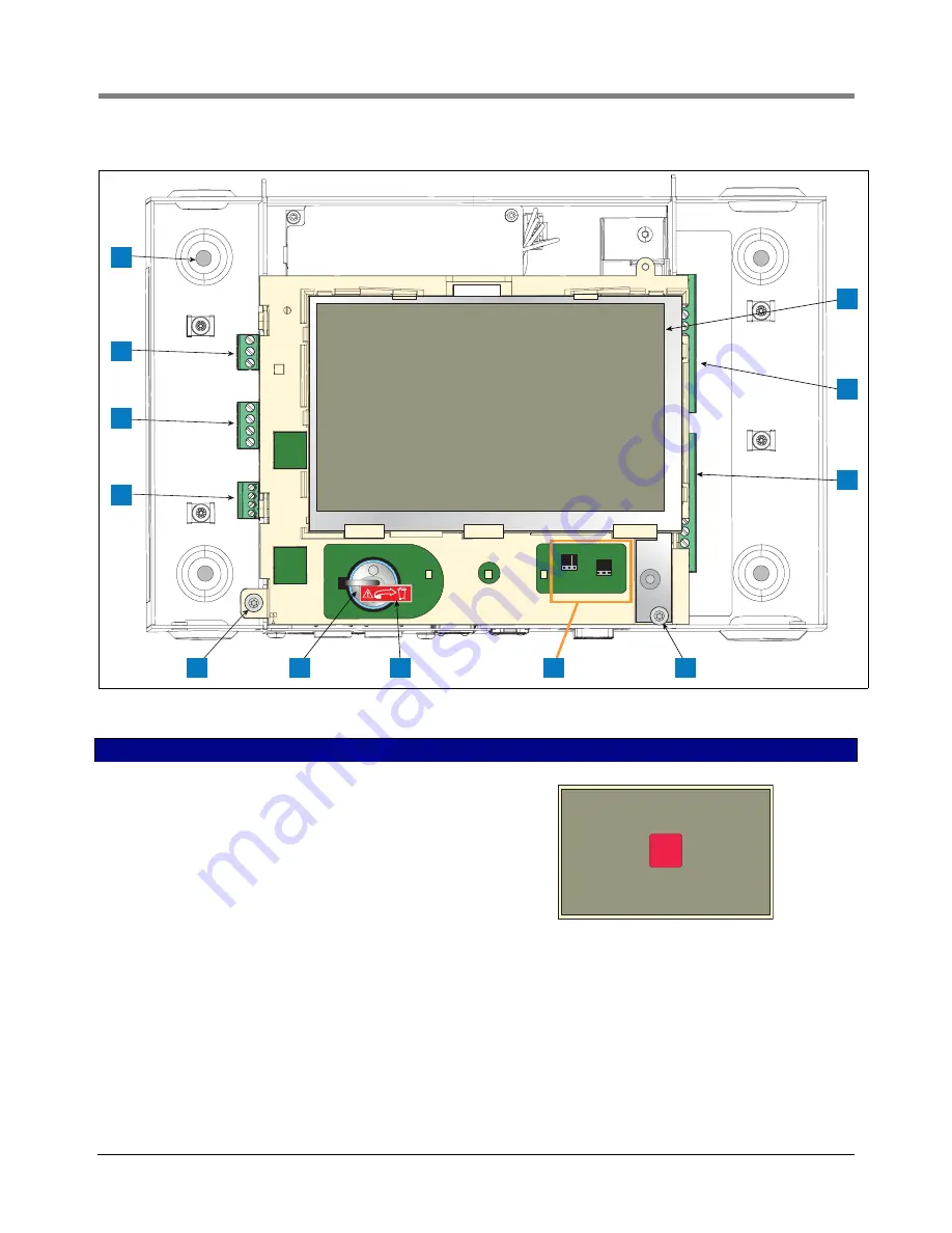
Figure 2.   Component Locations (Front Cover Removed)

LEGEND FOR NUMBERED BOXES IN Figure 2

1. AC or DC input power connector (as ordered)

2. High voltage output relay connector

3. Low voltage external input connector

4. T15 screw secures Display/CPU assembly 

5. Rechargeable 3V Lithium battery (battery backup)

6. RS232/485 selection jumpers SERIAL 1 (P1) and SERIAL 2 

(P2)(factory set to RS232 position)

7. T20 screw secures Display/CPU assembly

8. Optional 6-device intrinsically safe input connector (7 - 12)

9. Standard 6-device intrinsically safe input connector (1 - 6)

10. Optional Graphical User Interface (GUI) display (on non-dis-

play consoles, the GUI display is replaced with the Alarm

 Reset (Acknowledge) button panel shown below):

11. Battery Isolator - Remove and discard prior to startup.

12. Mounting Holes - 0.28” (7mm) diameter holes - (2 hole versions -

upper left and lower right corners; 4 hole versions - all four cor-
ners) .

3

1

12

2

4

6

7

8

P2 RS485

J39

J38

P2 RS232

P1 RS485

P1 RS232

9

+

+

10

5

11

ALARM

RE

S

ET

Содержание 8601 Series

Страница 1: ...Manual No 577014 022 Revision D Site Prep Certification Manual 8601 Series Console...

Страница 2: ...ur Terms and Conditions VEEDER ROOT S PREFERRED CARRIER 1 Contact Veeder Root Customer Service at 800 873 3313 with the specific part numbers and quantities that were missing or received damaged 2 Fax...

Страница 3: ...rsal Sensor Mounting Kit Introduction 1 Product Description 1 Kit Contents 1 Mounting Sensors 1 Appendix B Enabling The TLS4 To Function As A Datalogger BIR Protocol DIM 1 POS System Requirements and...

Страница 4: ...4 Ethernet Port Setup B 6 Figure B 5 Serial Port Setup SERIAL 2 POS B 6 Figure B 6 Entering ATG Command B 7 Figure B 7 Deleting ATG Command B 7 Figure B 8 TDIM Setup B 8 Figure B 9 Entering Host name...

Страница 5: ...nstalling UL cUL approved Mag Probes use Manual No 577013 744 Related Documents DOCUMENTS REQUIRED TO INSTALL EQUIPMENT This equipment must be installed according to the applicable installation docume...

Страница 6: ...R OFF Live power to a device creates a potential shock haz ard Turn Off power to the device and associated accessories when servicing the unit WARNING Heed the adjacent instructions to avoid damage to...

Страница 7: ...ual when mentioning any cable or wire being used for probe and sensor to console wiring it will be referring to shielded cable Wire Length Improper system operation could result in undetected potentia...

Страница 8: ...ratings and Form and Serial number 3 Intrinsically safe wiring conduit knockout 1 top 1 bottom 4 Optional touch screen display 5 Status LEDs 6 T15 screws secure cover 2 places 7 Communication ports s...

Страница 9: ...2 factory set to RS232 position 7 T20 screw secures Display CPU assembly 8 Optional 6 device intrinsically safe input connector 7 12 9 Standard 6 device intrinsically safe input connector 1 6 10 Optio...

Страница 10: ...ure 3 1 J36 Mode Jumper shown in Operating Mode Position 2 SD Card 3 Software Features iButton 4 Display ribbon cable connector Consoles with GUI display only 5 Acknowledge switch cable connector J40...

Страница 11: ...Universal AC power supply 100 to 249Vac 50 60Hz 2A maximum or DC power supply optional 24Vdc 2A max and 5Vdc 4A max Um 250Vrms or 250Vdc 240 Vac input 1 N L2 black 2 Ground green 3 L1 red 120 Vac Inpu...

Страница 12: ...E therefore a Null Cable is needed in order for communication to happen between the two consoles A Data Communication Equipment DCE device such as a modem may be connected directly to the interface us...

Страница 13: ...lug will have to be assembled in the field See TLS4 Troubleshooting manual P N 577014 058 for full instructions USB Ports 2 USB ports labeled USB 1 and USB 2 Item 7 in Figure 1 Expansion Port 10 pin c...

Страница 14: ...S Terminals 1 2 TLS4 I S Terminals 1 2 TLS4 I S Terminals Red Black White From Sensor Epoxy sealed connections in a weatherproof junction box Seal off Green Black White From Sensor Epoxy sealed connec...

Страница 15: ...C power WARNING FAILURE TO COMPLY WITH THE FOLLOWING WARNINGS AND SAFETY PRECAUTIONS COULD CAUSE DAMAGE TO PROPERTY ENVIRONMENT RESULTING IN SERIOUS INJURY OR DEATH Explosive vapors or flammable liqui...

Страница 16: ...ire rated for at least 90 C for barrier ground 3 Connect the input 120 or 240 Vac power wires as shown in Figure 5 Figure 5 Wiring AC Power to the Console LEGEND FOR NUMBERED BOXES IN Figure 5 1 Attac...

Страница 17: ...res for 24 Vdc 5Vdc and Ground and one 4 sq mm wire rated for at least 90 C for barrier ground 2 Connect the DC power wires as shown in Figure 6 Figure 6 Wiring DC Power to the Console LEGEND FOR NUMB...

Страница 18: ...location do not gang wires together i e splicing all sump sensor wires together to run one wire back to console Use single lengths of wire with no splices to ensure optimum signal strength WARNING FA...

Страница 19: ...ctices are acceptable by the authority having jurisdiction at this location The direct burial method requires grinding using an abrasive wheel a 1 4 to 3 8 wide by 1 1 4 deep groove adding 1 4 of dept...

Страница 20: ...1 Grade 2 Cord grip 3 Epoxy filled splice enclosure 4 Drill oversized hole in sump for DB cable 5 Dow Corning 890 SL silicone Pavement Sealant 6 Expanded polyethylene foam backer rod e g Applied Extr...

Страница 21: ...TLS4 is unfamiliar review the TLS4 Quick Help Guide P N 577014 034 or after the home screen displays touch the Actions icon then the Help icon to open the TLS4 console s online help Once online help d...

Страница 22: ...rsal Mounting Kit Contents Mounting Sensors Depending on the type of pan you are using you can configure the Universal Mounting Kit in several different ways Some of the more frequently used mounting...

Страница 23: ...zer tube to prevent excess clamping pressure on the sensor see Figure A 2 Figure A 2 Mounting the Sensor in a Stabilizer Tube to a Support Bar Sensor stabilizer tube Sensor Support bar sensors snstbtb...

Страница 24: ...rs A 3 Figure A 3 Mounting the Sensor in the Dispenser Pan sensors mntsndp eps Sensor Clamp Extender bracket Support bar 3 8 16 Spring nut 3 8 16 x 7 8 hex bolt 1 4 20 x 3 4 hex bolt w washer and nut...

Страница 25: ...nsor using Two Extension Brackets 3 8 16 Spring nut Support bar Extension bracket Extension bracket Clamp sensors extbkt eps Sensor 1 4 20 x 3 4 hex bolt w washer and nut 3 8 16 x 7 8 hex bolt 1 4 20...

Страница 26: ...Kit Mounting Sensors A 5 Figure A 5 Mounting the Sensor to Rigid Conduit U Bolt U bolt L bracket Clamp Sensor Rigid conduit sensors snlbkt eps 1 4 20 x 3 4 hex bolt w washer and nut not shown 1 4 20 x...

Страница 27: ...ing Kit Mounting Sensors A 6 Figure A 6 Mounting the Sensor to a Supply Line Supply line U bolt L bracket Sensor Clamp sensors snsupln eps 1 4 20 x 3 4 hex bolt w washer and nut not shown 1 4 20 x 1 1...

Страница 28: ...it Mounting Sensors A 7 Figure A 7 Mounting the Sensor in a Containment Sump Clamp L bracket Sensor Containment sump wall sensors sncntmnt eps 1 4 20 x 3 4 hex bolt w washer and nut not shown 1 4 20 x...

Страница 29: ...S consoles The following POS systems Table B 1 are known to have implemented the Veeder Root protocol and thus support BIR protocol DIM Dispenser Interface Module Datalogger Site Connection and Initia...

Страница 30: ...laptop or PC operating system used to configure this hardware In the Network Connections screen double click on the wired not wireless integrated Local Area Connection In the example below Figure B 1...

Страница 31: ...ization B 3 Figure B 2 Local Area Connection X Properties dialog box selections 5 When the Internet Protocol Version 4 TCP IPv4 Properties dialog box opens make the selections shown in Figure B 3 Firs...

Страница 32: ...ure B 3 Internet Protocol Version 4 TCP IPv4 Properties dialog box selections Click this radio button Enter this address Click OK button to save Click Close button changes close his dialog and return...

Страница 33: ...P address select Static IP and enter the IP address assigned by your network administrator Once this is complete click the Save button to keep these settings see example in Figure B 4 If the site is u...

Страница 34: ...B 5 Serial Port Setup SERIAL 2 POS 9 Go to the DLSetup application by clicking on white arrow in blue circle top center of screen see Figure B 6 and under System Setup click on ATG Commands 1 in Figur...

Страница 35: ...en Figure B 7 Deleting ATG Command 10 Select TDIM set up Select TDIM ETH1 from the drop down menu On the TDIM Enable drop down select TRUE and type in a label maximum of 20 characters Then select the...

Страница 36: ...ost name 12 In the Diagnostics page lower left in above figure click on DIM Communications to verify that the DIM communications are successfully being recorded by the Datalogger Any transactions occu...

Страница 37: ...ring Date and Time 14 From the System Setup menu click on the Units page 1 select the desired units 2 click Save 3 see example in Figure B 12 Figure B 12 Selecting System Units Select Click back arrow...

Страница 38: ...rom the completion of the previous step to allow for the system to re initialize with the new settings Then click on the Communication Testing link at the lower left bottom of the System Setup column...

Страница 39: ...en click on the Stop button see example in Figure B 17 Figure B 17 POS Protocol Type Results 19 The Datalogger should now be configured to collect inventory and transactional data which will be period...

Страница 40: ...has failed and you will need to contact FMS or the network administrator for troubleshooting assistance Figure B 18 FMS Heartbeat Screen IMPORTANT Connectivity between the Datalogger and FMS must be v...

Страница 41: ...For technical support sales or other assistance please visit www veeder com...

Отзывы: