


5
6
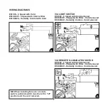
INSTALLATION
Fig 1: check there is nothing missing in box
and that instruction leaflet is included
Fig 2: drill hole in wall - minimum dia 99.8mm
-
allow extra width if using ducting -
it is the installer's responsibility to
use the appropriate core cutter to
obtain the correct hole diameter.
Fig 3:
use fan assembly as template to mark
drill holes -
NB
fan can be at any angle
Fig 4:
drill 3 x 6mm dia holes
Fig 5:
fit wall plugs
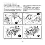
Fig 6:
decide whether to have cable access
from rear (recessed) or bottom (sur
face) of fan - if from bottom ensure that
included grommet is properly fixed
Fig 7: if cable is to come through rear of fan,
fit rubber ring (included)
Fig 8: gasket included for ceiling installation
Fig 9:
screw fan to wall
Figs 10, ll: make electrical connection using
cable clamp
Figs A: Wiring diagrams follow.
NB this fan is
double insulated and does not need
to be earthed
N.B This fan is NOT suitable for use with a
Gravity Grille. It should be installed using
either a Cowl or Fixed Grille.
Fig 12: Replace front cover
ES1003 - JUMPER SWITCH - 230v models
The ES1003 is
designed to run continuously
at one of 2 lower speeds fixed at installation
using the jumper switch. Fan supplied
ready for Speed 1 - lower speed. Installer
can change to Speed 2 if required. The
user can boost the fan speed to its maxi-
mum performance by using cord or remote
switch (when installing with remote switch,
pullcord switch must be left in "off" position
and cord removed).
NOTE: SELV products have a 3 pin jumper-
switch - see pages 8 and 9.
Содержание eSmile
Страница 5: ...5 ...