background image

User manual

 Document no. : 032189

 Version : V1.5

MC 785 CHILLER-2

 Customer: Heinen & Hopman

 Page: 11 of 16

6

Sensor calibration

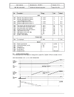
With parameters P1, P2, P41, P42, P43 and P44 the temperature sensors can be calibrated. 
If  a  temperature  sensor  readout  is  0.2

/

C  too  high,  for  example,  the  offset  of  the  appropriate

temperature sensor should be set 0.2

/

C lower.

The pressure sensors can be calibrated with parameters P12, P15, P18, P21, P24 and P27. 
If a pressure sensor readout is 0.3 bar too low, for example, then the offset of the appropriate pressure
sensor must be set 0.3 bar higher.

In addition, every pressure sensor has a 4mA and a 20mA value setting for setting its range.
For example: 

The  settings  for  a  pressure  sensor  with  a  range  of  0.00  ....  +10.00  bar and an
output of 4...20mA are as follows: The parameter for the value at 4mA must be set
at 0.00, and the parameter for the value at 20mA must be set at 10.00.

7

Alarms

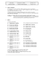
An alarm can be caused by:

E1

Temperature sensor-1 inlet defect.

E2

Temperature sensor-2 outlet defect.

E3

Pressure sensor-1 (HP2) defect.

E4

Pressure sensor-2 (OIL2) defect.

E5

Pressure sensor-3 (LP2) defect.

E6

Pressure sensor-4 (HP1) defect.

E7

Pressure sensor-5 (OIL1) defect.

E8

Pressure sensor-6 (LP1) defect.

E10    No contact with LMS extra sensors
E11    Temperature LMS sensor 1 too low
E12    Temperature LMS sensor 2 too low

E15 Temperature LMS sensor-1 defect
E16 Temperature LMS sensor-2 defect

E20 Too low pressure pressure sensor-6

compressor-1

E 21 Too low pressure pressure sensor-3

compressor-2

E22 Too high pressure pressure sensor-4

compressor-1

E23 Too high pressure pressure sensor-1

compressor-2

E24 Too low pressure pressure sensor-5 oil

pressure-1

E25  Too low pressure pressure sensor-2 oil

pressure-2

E26 Too low pressure pressure sensor-4

compressor-1

E27 Too low pressure pressure sensor-1

compressor-2

E30 Inlet temperature lower than outlet temperature

E31 Temperature sensor-1 inlet too low
E32 Temperature sensor-2 outlet too low

E33 Temperature sensor-1 inlet too high
E34 Temperature sensor-2 outlet too high

E40 Cabinet cooling failure
E41 Error waterflowswitch 1

E42 Chiller pump-1 failure
E43 Chiller pump-2 failure

E44 Compressor-1 failure
E45 Compressor-2 failure

E46 Maximum thermostat

E47 INT69-1 failure
E48 INT69-2 failure

E49 Sea pump-1 failure
E50 Sea pump-2 failure

E51 Error waterflowswitch 2
E52 Interlock cooling water fault

E60 Communication error LMS dig-in module-1
E61 Communication error LMS dig-in module-2
E62 Communication error LMS dig-in module-3

E63 Communication error LMS relay module-1
E64 Communication error LMS relay module-2
E65 Communication error LMS relay module-3

The alarm warnings can be seen in the temperature display (top left).

By pressing the 

RESET ALARM

 key the alarm relay can be reset. 

The error code continues to appear in the display as long as the fault remains.
The alarm LED will also continue to blink.

Содержание MC 785 CHILLER-2

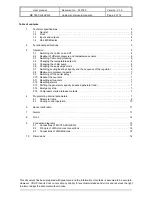
Страница 1: ...032189 Type MANUAL No of pages 16 Version V1 5 File Do032189 MC785 CHILLER v15 EN wpd Software 021913_MC785 CHILLER V2 02 By BJB Date 29 03 2012 VDH Products BV Roden Holland Signed File Doc 02 MC 785...

Страница 2: ...e sensors 6 3 3 Switching from cooling heating 6 3 4 Changing the temperature setpoint 6 3 5 Changing the chiller pump 6 3 6 Changing the sea pumps mode 6 3 7 Switching cooling heating capacity and th...

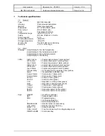
Страница 3: ...e oil pressure 1 alarm yellow Low 1 Alarm Failure low pressure 1alarm yellow High 2 Alarm Failure high pressure 2 alarm yellow Oil 2 Alarm Failure oil pressure 2 alarm yellow Low 2 Alarm Failure low p...

Страница 4: ...N 3 Failure sea water pump 1 NC potential free input contact Jumpers IN 4 Failure sea water pump 2 NC potential free input contact J2 IN 5 Maximum thermostat heating NC potential free input contact J1...

Страница 5: ...onal specifications The MC 785 CHILLER is a control system which brings the water for a heating or an airconditioning system to the desired temperature The MC 785 CHILLER has two pumps One of these pu...

Страница 6: ...setpoint can be changed by pressing the SET key The setpoint will now start to blink and the setpoint can be adjusted with the UP and DOWN keys The cooling setpoint can be set at between 5 C and 10 C...

Страница 7: ...re reset to zero 3 12 Resetting alarms As soon as an alarm situation occurs and an error code appears in the temperature display the alarm can be reset by pressing the RESET ALARM key The error code w...

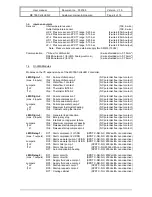
Страница 8: ...30 0 10 0 30 0 10 0 10 0 0 100 bar bar bar 0 0 25 0 0 0 10 P 26 P 27 P 28 P 29 Value OIL1 pressure sensor 5 at 4mA Value OIL1 pressure sensor 5 at20mA Offset OIL1 pressure sensor 5 Delay factor pressu...

Страница 9: ...compressor increases from 0 0 to 10 0 Volt Time in which the frequency of the compressor decreases from 10 0 to 0 0 Volt Anti shuttle time of compressors Delay before compressor 2 switches on 0 999 0...

Страница 10: ...ssure sensors Low pressure alarm real oil pressure Delay low pressure alarm real oil pressure High pressure too low alarm High pressure too low alarm delay Water flow alarm delay Number of flow switch...

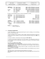
Страница 11: ...sor 1 defect E16 Temperature LMS sensor 2 defect E20 Too low pressure pressure sensor 6 compressor 1 E 21 Too low pressure pressure sensor 3 compressor 2 E22 Too high pressure pressure sensor 4 compre...

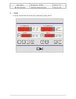
Страница 12: ...User manual Document no 032189 Version V1 5 MC 785 CHILLER 2 Customer Heinen Hopman Page 12 of 16 8 Front Front view of the MC785 CHILLER panel mounted model drawing 021773...

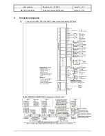
Страница 13: ...User manual Document no 032189 Version V1 5 MC 785 CHILLER 2 Customer Heinen Hopman Page 13 of 16 9 Connection diagrams 9 1 Connections of MC 785 CHILLER 2 panel mount drawing 021774w2...

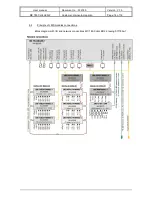
Страница 14: ...l Document no 032189 Version V1 5 MC 785 CHILLER 2 Customer Heinen Hopman Page 14 of 16 9 2 Principle of LMS modules connections Block diagram with I O and network connections MC 785 CHILLER 2 drawing...

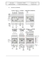
Страница 15: ...User manual Document no 032189 Version V1 5 MC 785 CHILLER 2 Customer Heinen Hopman Page 15 of 16 9 3 Connections of LMS Modules...

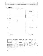
Страница 16: ...User manual Document no 032189 Version V1 5 MC 785 CHILLER 2 Customer Heinen Hopman Page 16 of 16 10 Dimensions Dimensions MC 785 panel mounted drawing 961271 Dimensions LMS modules...

Отзывы: