User manual
Document no. : 032189
Version : V1.5
MC 785 CHILLER-2
Customer: Heinen & Hopman
Page: 6 of 16
3
Operation
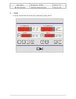
During normal operation the top left-hand display shows the INLET temperature, the top right-hand the
OUTLET temperature, and below left (SETPOINT) shows the OUTLET setpoint temperature.
The display below right (CAPACITY) shows the capacity currently being used for heating/cooling.
3.1
Switching the chiller on and off.
The regulator can be switched on or off by pressing the
ON/OFF
key.
3.2
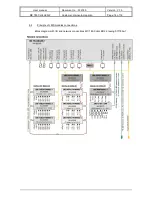
Readout of different pressure and temperature sensors.
By using the
PRESS SENS
key the values of the different pressure sensors will be shown
consecutively in the top left-hand display. With the help of the LEDs next to this display you can
see which sensor value is being shown.
If there is no LED on next to the display then the INLET temperature is shown on the display.
If the
PRESS SENS
key is then pressed once or more the exchange temperature sensors of the
LMS 4x10K/2xRH unit can be read consecutively. This is indicated by the ‘EC1..4' in the right-
hand display and the value of the sensor in the left-hand display.
3.3
Switching from cooling/heating.
If the
COOL/HEAT
key is pressed, the regulator will switch from cooling to heating or vice versa.
The LEDs next to the bottom left-hand display indicates whether the regulator is cooling or
heating.
3.4
Changing the temperature setpoint.
When the regulator is cooling the bottom left-hand display shows the current cooling setpoint.
When heating is taking place the heating setpoint is indicated there.
The setpoint can be altered by pressing the
SET
key. The regulator will now ask for the ‘user
password’. The ‘user password’ can be entered by using the
UP
and
DOWN
keys. If it is correct
the setpoint can be changed by pressing the
SET
key. The setpoint will now start to blink, and
the setpoint can be adjusted with the
UP
and
DOWN
keys.
The cooling setpoint can be set at between 5°C and 10
/
C, the heating setpoint at between 30°C
and 40
/
C. Now if no key is pressed for 30 seconds the setpoint will stop blinking and the new
septoint will become active.
3.5
Changing the chiller pump.
A switch can be made to the other chiller pump by means of the
PUMP1/2
key. All compressors
and heaters will be switched off while the regulator goes to the other pump. Then they will turn
themselves on again (with possible delay times). The LEDs next to the bottom left-hand display
indicate which chiller pump is in operation
3.6
Changing the sea pumps mode.
With the help of the sea pumps mode setting (P217) we can choose between two modes
P217=0:
Fixed couplings between sea pumps and compressors
Now sea-pump-1 belongs with compressor-1 and sea-pump-2 with compressor-2.
P217=1:
Choose for 1 sea pump
Now a choice can be made as to which sea pump will be used. The choice should be
made as follows: First, turn the regulator off with the
ON/OFF
key. Then use the
COOL/HEAT
key to choose which sea pump will be used, then the appropriate LED will
light up. When the choice has been made, the regulator can be turned on again.
3.7
Switching cooling/heating capacity and the sequence of the regulator.
By pressing the
CAP.LIMIT
key next to the bottom right-hand display the current maximum
heating capacity will be shown. The word ‘HEAT’ will appear in the display above to show that
we are dealing with heating. With the help of the
UP
and
DOWN
keys the capacity can be
adjusted.
If the
CAP.LIMIT
key is pressed once more the heater sequence appears in the display; a
different sequence can be selected with the
UP
and
DOWN
keys.
Next, press the
CAP. LIMIT
key once again and the capacity and the regulating sequence of the
cooling can be changed in a similar way.


