Vaughn TOP PERFORMER PLUS Скачать руководство пользователя страница 10

INSTALLATION CHECKLIST 


A. 

INSPECTING AND PREPARING THE HEATER 


Remove the cardboard box, which comes packaged with the 
heater. It should contain the following: Thermostat, T&P valve 
and “T” (no “T” for model S70DTPP), insulation, lid and screws.   


B.  LOCATION 


Solid foundation and dry location. 


Protect heater water lines from freezing. 


Area free of flammable vapors. 


Sufficient room to service heater. 


Not in close proximity to wood burning stove. 


Where leak will not damage property. 


C.  PROTECTION FROM WATER DAMAGE 


Be sure to make provisions to protect area from water 
damage if a leak should occur in the tank or connected 
fittings.  


D.  RELIEF VALVE 


Warning: Improper installation will present potential hazard 
to life and property. 


Check to be sure that proper relief valve requirements are met. 


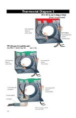
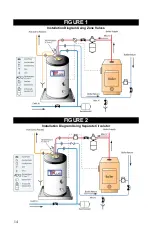
T&P installed as shown in Figures 1 and 2. (See Figure 3 for 
S70DTPP) 


3/4" discharge pipe 

– properly protected from freezing and 

restrictions. 


No valve between tank and relief valve or in drain line.  


Provision for hot water discharge from relief valve. 


E.  BOILER SUPPLY CONNECTIONS 


R

eturn line (back to the boiler) connected to the “Hx Out” fitting. 


Supply line (from the 

boiler) connected to the “Hx In” fitting. 


F.  WATER SUPPLY CONNECTIONS (See Figure 1 & 2). (See Figure 

3 for S70DTPP) 


Do not over tighten brass threads. 


Mark the water shutoff for future reference. 


Do not apply heat to cold inlet. 


If there is a check valve (sometimes in water meter), 
backflow preventer or pressure-reducing valve, install an 
adequate size expansion tank.


Содержание TOP PERFORMER PLUS

Страница 1: ...Operation and Installation Manual TOP PERFORMER PLUS Indirect Fired Water Heater Limited Warranty and Tank Replacement...

Страница 2: ...heaters will absorb less than 200 000 BTU hr when domestic water outlet temperature is 194 F and boiler water supply temperature is 240 F Listed outputs are based on ASME Section VIII Interpretation V...

Страница 3: ...ere is risk of property damage and personal injury inherent in the use of any hot water system The Company cannot supervise the installation and therefore makes it a specific condition of the warranty...

Страница 4: ...Diagram 5 ___________________________________________ 13 FIGURE 1_____________________________________________________ 14 FIGURE 2_____________________________________________________ 14 FIGURE 3____...

Страница 5: ...foundation in a clean dry location nearest the boiler The heater should be protected from freezing and water lines should be insulated to reduce energy and water waste Leave sufficient headroom to ser...

Страница 6: ...he requirements for Relief Valves and Automatic Gas Shutoff for Hot Water Supply Systems ANSI Z21 22 1971 This valve must be marked with maximum set pressure not to exceed the marked maximum allowable...

Страница 7: ...the other Thread the bolt into the nut and tighten in proper order See Figure 4 NOTE Be sure to place bolts in all of the openings WARNING Plastic o ring housing must be installed properly See Figure...

Страница 8: ...Supply Line from the boiler to the HX in fitting and Boiler Return Line to the boiler to the HX Out fitting H FILLING THE HEATER Check that the temperature and pressure relief valve has been properly...

Страница 9: ...ect 24VAC Power From the the switching relay board or from a step down transformer to the screws to the right of the Probe Connector See Thermostat Diagram 5 K TPI WIRING CONTROLS NOTE THE TPI THERMOS...

Страница 10: ...oper installation will present potential hazard to life and property Check to be sure that proper relief valve requirements are met T P installed as shown in Figures 1 and 2 See Figure 3 for S70DTPP 3...

Страница 11: ...trol temperature properly without any notice and therefore should be tested periodically for your protection DANGER IF YOU DISCOVER EXTREME HOT WATER COMING FROM THE FAUCET IMMEDIATELY SHUT OFF THE MA...

Страница 12: ...ee Thermostat Diagram 1 NOTE Markings on slide are approximate Check temperature at faucet to ensure safe operating temperature 4 Adjust left side lever to the desired differential The thermostat will...

Страница 13: ...ger Consists of two copper tubes one inside the other wound into a coil The outer tube is soldered into the brass fitting that mates into the tank The inner tube is soldered into the brass fitting tha...

Страница 14: ...11 Thermostat Diagram 1 Thermostat Diagram 2...

Страница 15: ...12 Thermostat Diagram 3 ETC101 Low Voltage Only Red Circuit Board TPI Green Circuit Board OUTPUT CONTACTS 24V IN...

Страница 16: ...and push wires Down into holes in top of connector This can also be done one side at a time 4 C Tug on each wire to make sure they are secure Wires Buttons Thermostat Diagram 5 Typical Wiring Wiring w...

Страница 17: ...14 FIGURE 1 Installation Diagram Using Zone Valves FIGURE 2 Installation Diagram Using Separate Circulator...

Страница 18: ...15 FIGURE 3 S70DTPP Installation Diagram Using a Single Tank S70DTPP Installation Diagram Including One Hotstow Storage Tank...

Страница 19: ...16 FIGURE 4...

Страница 20: ...If neither action has solved your problem please have your plumbing contractor contact us for assistance CUSTOMER RELATIONS DEPARTMENT General vaughncorp com 978 462 6683 VAUGHN THERMAL CORPORATION 26...

Страница 21: ...ANUFACTURED DATE INDICATED BY THE SERIAL NUMBER ON THE TOP PERFORMER COVERAGE Replacement policy covers only the storage tank for leaks caused by the corrosive effects of water under normal and proper...

Страница 22: ...and limitations 1 The Top Performer must be correctly installed according to the installation manual provided with the unit and all applicable local and national codes 2 The unit must be operated wit...

Страница 23: ...n should be noted At time of installation and retained for Future reference Model No Serial No Date Installed Dealer s Name Address City State Zip 26 Old Elm Street P O Box 5431 Salisbury MA 01952 543...

Страница 24: ...Warranty on newly purchased tanks Not available on replacement tanks may be purchased by completing and returning this form to Vaughn Thermal Corporation along with a payment of 199 within 30 days of...

Отзывы: