background image

3. Before Installing the System 


38                                         

Smart Plus (PHT-35LHS) Installation Manual   

Part 

No. 

Items 

Specification 

Figure 

QTY 

Comments 

Confirmed 

(OK?) 

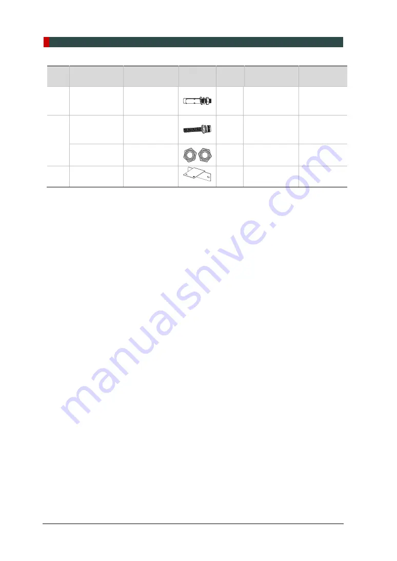
Anchor Bolt 

5/16 x 60 w/ 

Spring and 

Flat Washers 


10 

For Concrete 

Yes 

□ 

No 


35 

Wrench Bolt 

M8 x 25 w/ 

Spring and 

Flat Washers 


Yes 

□ 

No 


Nut 

M8 


Yes 

□ 

No 


36 

Wall Bracket 

Rear 


Yes 

□ 

No 


Содержание Smart Plus PHT-35LHS

Страница 1: ...Installation manual Model PHT 35LHS Version 1 29 English...

Страница 2: ......

Страница 3: ...us is in steady improvement The information contained in this manual may be subject to change without notice justification or notification of the persons concerned VATECH Co Ltd manufacturer reserves...

Страница 4: ...flat surface to maintain stability If the equipment is not stable property damage and personal injury may occur DO NOT push or pull the equipment Equipment should only be installed by an authorized te...

Страница 5: ...erlock Switch 21 2 8 Installing the Emergency Stop Switch 21 3 Before Installing the System 22 3 1 Required Tools 22 3 2 Checking the ShockWatch and TiltWatch Indicators 24 3 3 Unpacking Boxes 25 3 4...

Страница 6: ...Firewall Off 92 8 3 Setting up the Power Mangement Options 93 8 4 Turning off the User Account Control 95 8 5 Setting Folder Exclusions with Anti virus Software 96 9 Installing Software 97 9 1 Before...

Страница 7: ...n by the user s manual PC Software has been properly used by the manufacturer s installation instructions and user manuals 1 2 Customer s Responsibility Site planning and preparation are the responsib...

Страница 8: ...priate conditions or actions may cause Severe personal injury to the operator and patient Substantial property damage CAUTION Indicates that a potential hazard may exist which through inappropriate co...

Страница 9: ...1 Introduction Smart Plus PHT 35LHS Installation Manual 3 English Never touch or hold the sensor or tube head areas while moving installing or operating the equipment...

Страница 10: ...ile installing or operating the equipment DO NOT use the electric drill for tightening untightening screws Use it only for drilling a hole on the wall Grab the recommended holding areas only to transp...

Страница 11: ...1 1 3rd edition 2005 Any equipment not approved by VATECH must comply with the applicable standards IEC 60950 1 2nd edition 2005 for IT equipment Ex PC and IEC 60601 1 3rd edition 2005 for medical ele...

Страница 12: ...of this system shall comply with all local code requirements for electro medical systems IEC 60364 7 710 2002 It is strongly recommended that a UPS be installed at the same time as the equipment The...

Страница 13: ...quipment IEC60601 2 7 and IEC60601 2 28 X ray Tube Heads IEC60364 7 710 2002 Local Code Requirements for Electro Medical System Installation IEC 60601 1 1 2005 regulation shall be met to their full ex...

Страница 14: ...pplied Equipment IEC 60601 1 Degree of protection against leakage current and electric shock Class 1 equipment Label Radiation hazard Label Indicates the authorized representative in the European Comm...

Страница 15: ...be collected separately Label Warns ESD hazard MCU board Board package Indicates that this equipment is classified as a CLASS 1 LASER PRODUCT by IEC 60825 1 ED 2 regulations Label Indicates that the...

Страница 16: ...3 2008 IEC 60601 2 63 2012 21 CFR 1020 30 31 33 NEMA Standard publication PS 3 1 3 18 This is Class IIb equipment and obtained CE marking in April 2007 for regulations compliance in accordance with t...

Страница 17: ...the operator should be as about the patient as possible This equipment should not be installed on thick carpets for stability reasons Anti static floor materials should be used around the equipment T...

Страница 18: ...2 Choosing an Installation Site 12 Smart Plus PHT 35LHS Installation Manual With CEPH Unit optional 2805 9 mm L x 2 457 5 mm W or wider...

Страница 19: ...2 Choosing an Installation Site Smart Plus PHT 35LHS Installation Manual 13 English Ceiling Height 2 437 5 mm H or higher...

Страница 20: ...of the Entrance The door of the X ray room should have a clearance of more than 800 mm 31 5 wide Floor Area The floor of the X ray room must be stable and level for system balance The floor must be a...

Страница 21: ...ensure that the PC and equipment are connected to the same MPSO Use a dedicated power outlet for the power cord Failure to do so may result in unstable system operations caused by power fluctuations...

Страница 22: ...on panel with an over current circuit breaker rated for 20A must be used Maximally allowed deviation of the tube voltage tube current exposure time Tube Voltage kVp 10 Tube Current mA 20 Exposure Time...

Страница 23: ...17 English 2 4 Environmental Specifications Item Description During Operation Temperature 10 35 Relative humidity 30 75 Atmospheric pressure 860 1060 hPa During Transport and Storage Temperature 10 60...

Страница 24: ...are three options for installation depending on the configuration of the site Nevertheless the 2nd option is preferred Option No 1 The user operates the Exposure Switch from inside the X ray room Opti...

Страница 25: ...art Plus PHT 35LHS Installation Manual 19 English Option No 3 The 3rd party Exposure Switch not VATECH s is used on the demand of the customers For this scenario see Appendix D Connecting the 3rd part...

Страница 26: ...2 Choosing an Installation Site 20 Smart Plus PHT 35LHS Installation Manual 2 6 Installation Versions Base stand Type Wall mount Type...

Страница 27: ...nergized The warning lamp and Door Interlock Switch are not included with the equipment The warning lamp and the Door Interlock Switch must be installed by a qualified technician 2 8 Installing the Em...

Страница 28: ...Appendix F Installation Checklist 3 1 Required Tools The following tools are necessary to install the Smart Plus Item Figure Size Wrench Set 1 5 mm 10 mm 0 06 0 4 T shaped Hex Wrench 6 mm 10 mm 0 24 0...

Страница 29: ...on Manual 23 English Item Figure Size Anti Static Glove N A Knife N A Tape Ruler for Wall Mount type 5 m Marker Pen thick tip for Wall Mount type N A Hammer for Wall Mount type N A Multimeter N A Hamm...

Страница 30: ...ical shock or impact during transportation However the red indicator does not exactly mean that the equipment has been damaged These indicators are affixed only to the main box which contains the equi...

Страница 31: ...I detector The digital CBCT system is based on a CMOS digital X ray detector The CMOS CT detector is used to capture 3D radiographic images of the head neck oral surgery implant and orthodontic treatm...

Страница 32: ...eparate the top cover after removing the strapping bands 3 Lift a small distance remove the side covers 4 Remove the plastic wrap covering the box by using a cutter While one installer is removing a s...

Страница 33: ...3 Before Installing the System Smart Plus PHT 35LHS Installation Manual 27 English PANO Box Configuration CEPH Box Configuration...

Страница 34: ...tion 1 Pull out the upper and lower carrying handles from EPS Main Base 2 Assemble the upper carrying handle by using one wrench bolt Wrench Bolt M8 x 25 2 Sems 1 pcs Allen Wrench 6 mm 0 24 The Wrench...

Страница 35: ...ch Bolt M8 x 30 2 pcs Allen Wrench 6 mm 0 24 The Wrench Bolt is attached to the Column unit Remove the bolts from the Column first 4 Remove the EPS Main Right and EPS Main Left as follows 1 Remove the...

Страница 36: ...t the Main Unit with the EPS Main Base on a Transport Dolly and move it to the installation site When putting the Main Unit on the dolly make sure that the center of the mass indicator is aligned with...

Страница 37: ...S Installation Manual 31 English 3 3 2 Box No 2 Base Unit Component Size mm inch Weight kg lbs Base 1035 L x 1025 W x 185 H 40 7 L x 40 3 W x 7 3 H 65 143 Removing the cover 1 Open the box cover and r...

Страница 38: ...S Installation Manual 3 3 3 Box No 3 CEPH Unit Optional Component Size mm inch Weight kg lbs CEPH unit 1590 L x 820 W x 870 H 62 6 L x 32 3 W x 34 3 H 50 110 Removing the cover 1 Open the box cover an...

Страница 39: ...3 Before Installing the System Smart Plus PHT 35LHS Installation Manual 33 English 3 4 Checking the Parts 3 4 1 Location Layout of the Parts and Accessories...

Страница 40: ...No 2D Viewer Manual 1 For EasyDent i or EzDent Yes No 3D Viewer Manual 1 For Ez3D i or Ez3D Plus Yes No Installation USB 1 Yes No License Key 1 For Ez3D i and EzDent i Yes No 2 Exposure Switch 1 Yes N...

Страница 41: ...available in some Asian countries Yes No Special A 1 Yes No Special B 1 Yes No 9 Chinrest Normal 1 Yes No 10 Left Blank Intentionally 11 Sanitary Vinyl Cover For Normal Bite 1 Yes No 12 Left Blank In...

Страница 42: ...System Optic Cable 1 Yes No LAN Cable 1 Yes No IFG Card or FTG Card or LEG Card 1 Yes No MODEL Scan Jig 1 For the 3D MODEL Scan model Yes No 22 Column Bracket 1 Yes No 23 Wrench Bolt M10 x 25 w Sprin...

Страница 43: ...No 30 Set Screw M10 x 20 4 Yes No 31 Protractor 1 Yes No Wall Plate 1 Yes No Terminal Block 3 Pole 1 Yes No 32 Middle Bracket 1 Optional Yes No Wrench Bolt M8 x 25 w Spring and Flat Washers 2 Yes No...

Страница 44: ...Installation Manual Part No Items Specification Figure QTY Comments Confirmed OK Anchor Bolt 5 16 x 60 w Spring and Flat Washers 10 For Concrete Yes No 35 Wrench Bolt M8 x 25 w Spring and Flat Washers...

Страница 45: ...cification Figure Qty Comments Location Confirmed OK Base Front Cover N A 1 N A On the upper side of the EPS Main Bottom Yes No Column Back Cover N A 1 N A On the upper side of the EPS Main Bottom Yes...

Страница 46: ...e is a concrete floor go to section 4 4 Fixing the base Optional and do number 1 first after that turn back 4 1 Assembling the Base and Main Units 1 Remove the lower carrying handle Allen Wrench 6 mm...

Страница 47: ...in the bolts as shown in the figure Hold the base unit to keep it from falling 4 Put the base unit to the column unit by engaging the base holes in the bolts as shown in the figure Allen Wrench 6 mm...

Страница 48: ...lus PHT 35LHS Installation Manual 5 Tighten the two wrench bolts Allen Wrench 6 mm 0 24 6 Put the equipment in a vertical position slowly while holding the upper handle DO NOT damage the cables Before...

Страница 49: ...ling the Equipment Base Stand Optional Smart Plus PHT 35LHS Installation Manual 43 English 7 Tighten the three wrench bolts to attach the base unit Allen Wrench 8 mm 0 31 Wrench Bolt M10 x 25 3 pcs Pa...

Страница 50: ...ensor and tube head 1 Now it is assumed that the CEPH box has already been opened 2 Remove the plastic wrap covering the column unit and the tape for fixing the CEPH cables by using a cutter 3 Move an...

Страница 51: ...uipment Base Stand Optional Smart Plus PHT 35LHS Installation Manual 45 English 4 Tighten the three wrench bolts to attach the base unit Allen Wrench 8 mm 0 31 Wrench Bolt M8 x 20 3 pcs Part No 25 Fla...

Страница 52: ...e cables as shown in the figure When managing the fiber optic cable DO NOT bend pull or crush it Ensure that the caps of the fiber optic cable have been removed DO NOT touch the tip of the fiber optic...

Страница 53: ...PHT 35LHS Installation Manual 47 English 6 Put the cables inside the CEPH Arm and assemble the CEPH arm cover by using two flat head screws Cross Head Screwdriver w Magnetic Tip 6 mm 0 24 Flat Head S...

Страница 54: ...roperly installed Otherwise the equipment may be shaken during the scanning 1 Move the equipment to the installation site near the wall 2 Remove the lower carrying handle Allen Wrench 8 mm 0 31 One in...

Страница 55: ...and Optional Smart Plus PHT 35LHS Installation Manual 49 English 5 Assemble the column bracket to the top ofthe column with four flat head screws Cross Head Screwdriver w Magnetic Tip 6 mm 0 24 Flat H...

Страница 56: ...e the wall bracket Wall Bracket Part No 36 Wall Bracket for Wood Wall Optional Part No 37 2 Combine the column and wall brackets in the following manner with the 2 wrench bolts Allen Wrench 8 mm 0 31...

Страница 57: ...nual 51 English Marking Points on the Wall 1 Move the equipment to the installation site as close as possible 2 Adjust the distance between the wall and equipment by moving it slightly so that the wal...

Страница 58: ...wall holes of size 10 5 mm x 30 mm depth using the concrete hammer drill 2 Remove the debris and clean the holes using the dust pump 3 Using the hammer insert a Ficher strong anchor into the hole Fich...

Страница 59: ...English Combining the Equipment with the Anchor Bolts 1 Place the equipment on the alignment plate while observing 4 Hex bolts are being appropriately inserted through each hole Hex Bolt M8 x 15 Spri...

Страница 60: ...g and Flat Washers 2 pcs Part No 34 Hammer Drill L 200 mm 7 9 Hammer N A Ratchet Wrench Tips 3 mm 8 mm 0 12 0 3 1 Before installing the equipment put the base unit on the installation site and mark 2...

Страница 61: ...PHT 35LHS Installation Manual 55 English 4 Remove nuts and washers put the anchor bolts into the holes 5 Secure the anchor bolts with the hammer 6 Place the base unit combined equipment in the proper...

Страница 62: ...stalling the Equipment Base Stand Optional 56 Smart Plus PHT 35LHS Installation Manual Wooden Floor Wood Screws M12 x 70 2 pcs Part No 34 Hammer Drill L 200 mm 7 9 1 Secure the base unit using wood sc...

Страница 63: ...4 5 Connecting the Cables to the Equipment 1 Connect the cables in the back of the column as shown in the figure Optic Cable Cable No H000014A Part No 21 Cable Tie Part No 20 Exposure Switch Part No...

Страница 64: ...Plus PHT 35LHS Installation Manual 2 Assemble the Column Back Cover with four truss bolts Truss Bolt M4 x 8 2 pcs Part No 27 Cross Head Screwdriver w Magnetic Tip 6 mm 0 24 3 Ensure the cables go thr...

Страница 65: ...t Plus PHT 35LHS Installation Manual 59 English 4 6 Removing the Transportation Safety Bolts 1 Remove the two column fixing bolts including the tags Allen Wrench 6 mm 0 24 2 Remove the semi clear tape...

Страница 66: ...nual 3 Remove the Vertical Frame Cover 4 Remove four Safety Bolts and two Safety Brackets including the tags Allen Wrench 6 mm 0 24 Be sure not to damage the cables when removing the bolts The Safety...

Страница 67: ...irit Level N A Ensure that the Spirit Level should rest only on the locations indicated in the following figures to obtain the accurate center 1 Prepare the Spirit Level 2 Turn the Rotating Unit clock...

Страница 68: ...2 Smart Plus PHT 35LHS Installation Manual Leveling Right and Left 1 Place the Spirit Level as shown in the figure 2 Adjust the base until the bubble on the Spirit Level centers in the middle by turni...

Страница 69: ...own in the following figure 2 Adjust the screws until the bubble of Spirit Level centers level by turning the front and back screws clockwise or vice versa 3 When the leveling is completed make sure t...

Страница 70: ...he Equipment You are advised to plan and study the installation environment carefully in advance before proceeding since the installation involves drilling the wall and floor Pre installation planning...

Страница 71: ...LHS Installation Manual 65 English Marking Points on the Floor 1 Put the aligning plate on the floor near the wall where the equipment should be installed as shown in the figure Alignment Plate Part N...

Страница 72: ...Drill the floor holes size 10 5 x 30 mm by using the concrete hammer drill 3 Remove the debris and clean the holes withthe dust pump 4 Put the anchor bolts into the holes and attach them with the ham...

Страница 73: ...nchor Bolts 1 Put the aligning plate on the floor and ensure that all anchored bolts come through the holes on the plate 2 Put the equipment in a vertical position slowly while holding the upper handl...

Страница 74: ...the anchored bolts 4 Put the washers and nuts into the six anchored bolts on the floor and tighten the nuts loosely Make sure that you put the fasteners in the sequence as shown in the figure DO NOT...

Страница 75: ...5 3 Installing the Wall and Column Brackets Assembling the Column Bracket 1 Move the equipment to the installation site near the wall 2 Remove the lower carrying handle Allen Wrench 6 mm 0 24 One inst...

Страница 76: ...Wall Mount 70 Smart Plus PHT 35LHS Installation Manual 5 Assemble the column bracket to the top ofthe column with four flat head screws Cross Head Screwdriver w Magnetic Tip 6 mm 0 24 Flat Head Screw...

Страница 77: ...e the wall bracket Wall Bracket Part No 36 Wall Bracket for Wood Wall Optional Part No 37 2 Combine the column and wall brackets in the following manner with the 2 wrench bolts Allen Wrench 6 mm 0 24...

Страница 78: ...Manual Marking Points on the Wall 1 Move the equipment to the installation site as close as possible 2 Adjust the distance between the wall and equipment by moving it slightly so that the wall bracke...

Страница 79: ...all holes of size 10 5 mm x 30 mm depth using the concrete hammer drill 2 Remove the debris and clean the holes using the dust pump 3 Using the hammer insert a Ficher strong anchor into the hole Fiche...

Страница 80: ...Combining the Equipment with the Anchor Bolts 1 Place the equipment on the alignment plate while observing 4 Hex bolts are being appropriately inserted through each hole Hex Bolt M8 x 15 Spring washer...

Страница 81: ...S Installation Manual 75 English 5 4 Connecting the Cables to the Equipment Please refer to section 4 5 Connecting the Cables to the Equipment 5 5 Removing the Transportation Safety Bolts Please refer...

Страница 82: ...the following figures to obtain the accurate center 1 Prepare the Spirit Level 2 Turn the Rotating Unit clockwise so that the X ray tube head faces the front as shown in the figure 3 Put the set scre...

Страница 83: ...ng the Equipment Wall Mount Smart Plus PHT 35LHS Installation Manual 77 English 5 Turn each set screw clockwise or counterclockwise to make the equipment level while another person monitors the level...

Страница 84: ...Equipment Wall Mount 78 Smart Plus PHT 35LHS Installation Manual 5 7 Tightening the Bolts 1 Tighten the joint bracketbolts Allen Wrench 6 mm 0 24 Monkey Wrench N A 2 Tighten the nuts in the anchored b...

Страница 85: ...nual 79 English 6 Completing Miscellaneous Works 6 1 Assembling Various Covers Base Cover Optional Truss Bolt M5 x 8 3 pcs Part No 26 Base Cap 3 pcs Part No 17 1 Assemble the base cover and fix it wit...

Страница 86: ...you do not use the base during the installation remove 2 pcs of Truss bolts while installing the front cover as below Truss Bolt M4 x 8 2 pcs Part No 27 Silicon Cap 2 pcs Part No 16 1 Assemble the ba...

Страница 87: ...ts and the Chinrest Assembling the Temple Supports and the Bite Block should be done after acquiring a test image is completed 1 Insert the normal Chinrest and the normal Bite Block into the unit Chin...

Страница 88: ...o 33 Truss Bolt M4 x 10 2 pcs Part No 33 UP DOWN Front Cover 1 Assemble the UP DOWN Switch Holder on the bottom of the Vertical Frame with two Truss Bolts M4 x 10 2 Connect the UP DOWN switch to the u...

Страница 89: ...Installation Manual 83 English 7 Setting up PC 7 1 Direct Connection Diagram Fiber Optic Cable Used to transfer image data to thePC Warning System Panel Used to provide a visible indicator Light on wh...

Страница 90: ...egulator to keep the line voltage stable The PC system provided with the Smart Plus undergoes the rigorous test for software compatibility before shipping Therefore any later changes to the hardware a...

Страница 91: ...ot enabled Windows 10 is not protected from malware and virus Disabling Windows Defender 1 Open the Start screen type Windows Defender in the search box 2 Click the Windows Defender icon to start Wind...

Страница 92: ...7 Setting up PC 86 Smart Plus PHT 35LHS Installation Manual 5 On Select Folder window type C VcaptureSW in the folder field and click Exclude this folder...

Страница 93: ...power cord from the main outlet or PC Disregard this section in case the PC system is supplied with the equipment The peripherals have already been installed inside the PC Whenever managing the fiber...

Страница 94: ...3 Insert the frame grabber Part No 21 carefully into that PCIe2 x 4 slot and lock it IFG Card or FTG Card or LEG Board Double check the locking status between the board and its holder after the board...

Страница 95: ...ition arise from the bad cable or its bad contact condition Connect the regular cables for PC keyboard mouse and video in advance The following figures and descriptions are based on the PC model Z4 fr...

Страница 96: ...7 Setting up PC 90 Smart Plus PHT 35LHS Installation Manual 4 Confirm the result after connections are as same as below The illustrations may differ from the actual product...

Страница 97: ...r USB imputation of images should be installed on the formatted PC where no other program s except the operating system OS is present Before InstallShield installation ensure that the video card drive...

Страница 98: ...or this reason it is required to disable the Windows Firewall by using the following procedures 1 Open the Start screen type Windows Firewall in the search box 2 Click the Windows Firewall icon to sta...

Страница 99: ...s To avoid disruptive and abnormal operation while acquiring an image it is required to reconfigure some parameters on the Windows operating system Disable the Screen Saver 1 Open the Start screen typ...

Страница 100: ...ual Selecting the Power Options Monitor and System 1 Open the Start screen type Power Options in the search box 2 Click Choose when to turn off the display 3 Select Never for both Turn off the display...

Страница 101: ...LHS Installation Manual 95 English 8 4 Turning off the User Account Control 1 Open the Start screen type User Account Control in the search box 2 Disable the UAC by moving the slider bar down to the b...

Страница 102: ...scans performed by the anti virus software For Smart Plus the following folders and files inside for relevant software should be excluded from the virus scan Path Software C ProgramFiles Vatech Ez3D i...

Страница 103: ...ed Downloading irrelevant programs to the same PC may cause conflicts between programs and result in equipment failures The image viewer program such as EzDent i EasyDent or the one from the 3rd party...

Страница 104: ...l 9 2 Software Installation Flow 9 3 Installing Image Viewer Program One of the image viewer programs among the EzDent i EasyDent or 3rd party program must be installed at this time For the details on...

Страница 105: ...lease check the serial number txt e g 047 011752 txt file 1 Turn on the PC and the equipment if they are not yet 2 Insert the USB drive into the USB connector and then perform a virus scan for the PC...

Страница 106: ...ecked as below If the CEPH feature is not included in the equipment uncheck the CEPH option Moreover click Next 7 Confirm that the WidePano is selected in the CBCT sensor type selection window and cli...

Страница 107: ...on window and clickNext 10 Select the default port number COM2 Select the port number COM2 The same COM port number should be used between the equipment and PC 11 Select the language and click Next 12...

Страница 108: ...Next to continue When EasyDent is installed select EasyDent when EzDent i is installed selectSDK 14 Check the options according to the product specifications When the AutoSave is checked the image da...

Страница 109: ...PHT 35LHS Installation Manual 103 English 16 You can check the information entered so far with the Ready to Install window If necessary you can modify it by clicking Back 17 When the information is co...

Страница 110: ...nual Installing the DICOM Viewer 1 After completing basic settings the DICOM Viewer installation will be started Click Next in the Welcome window 2 Select I accept the terms of the license agreement a...

Страница 111: ...9 Installing Software Smart Plus PHT 35LHS Installation Manual 105 English 4 From the next screen click Install 5 Click Finish to exit the wizard...

Страница 112: ...lus PHT 35LHS Installation Manual Installing the DirectX 1 After completing the DICOM viewer installation DirectX installation will be started Select I accept the agreement in the Welcome window 2 Cli...

Страница 113: ...9 Installing Software Smart Plus PHT 35LHS Installation Manual 107 English 3 Click Finish to exit the wizard...

Страница 114: ...Inform Grabber 1 After completing the Direct X installation Virtual Serial installation will be started Click Install in the Welcome window 2 During installation VA_4x Cap 1 1 installation wizard wil...

Страница 115: ...sual C 2010 x64 Redistributable installation or maintenance window will appear Select one of the options and click Next to continue the process 6 Click Finish to exit the Visual C 2010 x64 Redistribut...

Страница 116: ...fter completing the Direct X installation Grabber Driver Setup will be started Select the language in the installer language window and press the OK button 2 When the Grabber Driver Setup window appea...

Страница 117: ...appear and disappear and the Completing Grabber Driver Setup window will appear Choose the Reboot now or I want to reboot later and click the button manually If an error occurs during installation it...

Страница 118: ...the installation program will be started Select the language in the installer language select window and press the OK button 2 Press the V Grabber s Install button 3 The installation is completed and...

Страница 119: ...nstall_Log txt on the desktop 2 Open it to check the file You can find out that all components are installed 3 Go to section 9 5 Setting up the User specific Information Uninstalling Software 1 Open t...

Страница 120: ...m EasyDent or EzDent i SDK installed on the PC EasyDent Refer to Section 9 5 1 when the EasyDent is installed EzDent i Refer to Section 9 5 2 when the EzDent i is installed 9 5 1 When the EasyDent is...

Страница 121: ...n Manual 115 English Interfacing the EasyDent with Imaging Program One time Linking 1 On the main screen of the EasyDent click Help Configuration 2 Click on the Program tab 3 Check Select capture mode...

Страница 122: ...Installing Software 116 Smart Plus PHT 35LHS Installation Manual 4 Click on the button for the Path and select the Console SW s executable file 5 The Path is displayed as shown in the following figur...

Страница 123: ...ware Smart Plus PHT 35LHS Installation Manual 117 English 6 Check Select capture mode for panorama and select Etc from the drop down list 7 Click on the button for the Path and select the Console SW s...

Страница 124: ...35LHS Installation Manual 8 The Path is displayed as shown in the following figure 9 Click Apply 10 When the following message appears click OK to restart the program 11 Re run the EasyDent program an...

Страница 125: ...nying EasyDent Manual 1 Click the Patient icon on the upper left corner of EasyDent s main GUI window 2 Then the following dialog box will be displayed Enter the required patient information Chart No...

Страница 126: ...imaging program the registration window will be displayed 1 Click Next to proceed 2 Select I agree to the Vatech Privacy Policy and click Next 3 Enter the required information and click Next For the...

Страница 127: ...ole PC connected to the Internet 4 Click Finish For the Console PC NOT connected to the Internet 1 Click Download file to download and save the file HTML type into a memory device 2 Execute the file i...

Страница 128: ...re 122 Smart Plus PHT 35LHS Installation Manual 4 Download auth Acer file 5 Copy the downloaded auth cert file to the console PC 6 Click the Upload Verification file to upload auth cert file 7 Click N...

Страница 129: ...rner of EasyDent s main window to open the imaging program 2 The main screen of the selected mode is displayed From the main screen you can configure the imaging parameter settings before acquiring an...

Страница 130: ...nstallation Manual 9 5 2 When the EzDent i is installed This program must be run in administrator mode Running the Image Viewer 1 Run the image viewer On your desktop double click the EzDent i icon Th...

Страница 131: ...Smart Plus PHT 35LHS Installation Manual 125 English Interfacing the EzDent i with Imaging Program One time Linking 1 On the main screen of the EzDent i click EzDent i Setting 2 Click Acquisition Con...

Страница 132: ...3 Make sure that the console program settings are as follows Console Program Path C VCaptureSW exe VCaptureSW exe Capture Message Smart Plus Captured Patient Information File Path C VCaptureSW Patien...

Страница 133: ...ect refer to the accompanying EzDent i Manual 1 Click on the Add Patient button from the PATIENT tab 2 Enter the required patient information Chart Number First Name and Last Name are required fields...

Страница 134: ...differently depending on the equipment s capacity for acquiring images 2 Select the imaging mode Then the main GUI in the selected imaging mode appears The error code E033 indicates that the equipment...

Страница 135: ...tered following the user requirements 1 From the main GUI window click the settings icon in the upper right corner 2 Log in the tap will be open by default On the right side of the screen select Engin...

Страница 136: ...the following figure 6 In the DAP check that the default DAP Level and DAP Unit are displayed as shown in the following figure 7 In the Language Option the default language setting is English If nece...

Страница 137: ...formation Setting configure the Link Type File Path and File Name as shown in the following figure 10 In the Link Information Setting configure the Link Type and File Extension as below Fields When Ea...

Страница 138: ...132 Smart Plus PHT 35LHS Installation Manual 11 Click on the Default tab and configure the user defined parameters The default features can be modified according to the user s requirements 11 Click Sa...

Страница 139: ...ed the equipment will not be operated even after being turned on 1 Click on the General tab on the Control Panel 2 In the Networking option enable the Serial checkbox and set Serial port and Baud Rate...

Страница 140: ...PKEN_0000 to exit the packing mode Now note that the equipment is out of the packing mode Use the command PKEN_0001 to re enter the packing mode 5 Click Exit and terminate the Control Panel 6 Importan...

Страница 141: ...PANO Music Different for each mode 0001 CT PANO Music Same for each mode 0002 Default CT PANO Beep Same for each mode 1 Send the command following the command specification as specified in the table...

Страница 142: ...9 Installing Software 136 Smart Plus PHT 35LHS Installation Manual Finalizing the Parameter Settings 1 Click Exit Close and terminate the Control Panel 2 Important Exit the imaging program main GUI...

Страница 143: ...Smart Plus PHT 35LHS Installation Manual 137 English 10 Technical Specifications 10 1 Mechanical Specifications Dimensions unit mm With CEPH unit Without CEPH unit Top view Side view Wall bracket dime...

Страница 144: ...t Without CEPH unit 1144 3 L x 1557 5 W x 2306 H mm without Base 45 1 L x 61 4 W x 90 8 H inch without Base 1144 3 L x 1557 5 W x 2337 5 H mm with Base 45 1 L x 61 4 W x 92 1 H inch without Base With...

Страница 145: ...uracy Tube Voltage kVp 10 Tube Current mA 20 Exposure Time s 5 50 ms The input line voltage depends on the local electrical distribution system Allowable input voltage fluctuation requirement 10 Mode...

Страница 146: ...allation Manual 10 3 Environmental Specifications Item Description During Operation Temperature 10 35 Relative humidity 30 75 Atmospheric pressure 860 1060 hPa Transport and Storage Temperature 10 60...

Страница 147: ...agreed with the local radiation protection advisor RPA customer 3 A fluorescent lamp shall not be used in the X rays on sign 4 The customer shall be responsible for the proper installations for the wa...

Страница 148: ...Appendix A 2 Smart Plus PHT 35LHS Installation Manual Schematic Diagram Components Supplied...

Страница 149: ...m 198 Warning lamp 1 m 40 Power source cable 1 m 40 1 Prepare the Warning System Panel Part No 28 2 Install the Warning System Panel at the proper height after taking each cable length into account 3...

Страница 150: ...the emergency case but cannot be pushed by mistake The switch shall be a type of mistake proof The switch is not supplied The switch shall be installed at a height of 1 2 to 1 5 meters 47 to 60 1 The...

Страница 151: ...t This section explains how to limit the column height within the permissible range 1 Measure the ceiling height in the X ray shield room Hceiling Removing the column covers 2 Remove two Fixing Bolts...

Страница 152: ...he top of the equipment when the column is fully extended d Hceiling HMax Hceiling 2306 mm Example height The height of the equipment without Base Ex If Hceiling is 2200 mm Hscrew height value is calc...

Страница 153: ...m the default current position to the new one 1 Loosen two bolts halfway important DO NOT unscrew completely the bolt If not it could drop into the column and may cause big trouble to retrieve it out...

Страница 154: ...connect the third party Exposure Switch with the equipment from VATECH How to 1 Cut the Exposure Switch cable provided with the equipment 2 According to the following schematic diagram rewire the cabl...

Страница 155: ...C BIOS Settings HP PC BIOS Setup PC Model HP Z4 PC BIOS default Main Menu Sub1 Menu Sub2 Menu Setup Value Advanced Power Options Runtime Power Management Disable Advanced Power Options Idle Power Savi...

Страница 156: ...anual F Installation Checklist 1 General Information Customer Information about the Equipment Purchaser Name of Clinic or Hospital Address Phone E Mail Website Dealer Information about the Equipment S...

Страница 157: ...stallation Date of installation Model Serial No 3 System Delivery to Site Yes No Did you review and identify the delivery route and method for equipment in advance Is the freight elevator available Is...

Страница 158: ...Does the electrical input condition to the installationsite meet the MEIGaN requirements Is the local Network IP address of clinic 192 168 33 xx Is a compressor or air conditioner suction located righ...

Страница 159: ...ny suspicious holes or scratches on the box after opening 5 While Installing Equipment Yes No Are installers careful with any sensitive parts while carrying equipment Did the installers make sure that...

Страница 160: ...Do the equipment Up Down switch works properly 7 Software Compatibility Yes No Anti virus software installed A firewall installed If yes indicate software or hardware Type Is the 3rd party software i...

Страница 161: ...Configuration Yes No Is a network configured with 1 Gbit s of CAT5 Is the equipment connected to thenetwork Is the network installation company identified What is the TCP IP addressassigned Address W...

Страница 162: ...Appendix A 16 Smart Plus PHT 35LHS Installation Manual Intentionally left blank...

Страница 163: ...n permission of the manufacturer We reserve the right to make any alterations that may be required due to technical improvement For the most current information contact your VATECH representative Tel...

Страница 164: ......

Страница 165: ...www vatech com...

Отзывы: