Installation
Varec, Inc.
47
Reassembly
1. Reinstall the covers, gaskets, and bolts on the elbows.
2. Close the tank manholes and inspection covers.
Installation of Model 226 for 20 and 24 Inch
Manhole Covers with API Drilling
See Figure 2 on page 33 to install Model 226 20 inch (Part Number BM3443) and 24 inch (Part
Number BM3607) manhole covers with API drilling.
1. Remove the existing manhole cover.
2. Separate the Model 226 cover by removing the flange connecting bolts.
3. Install the cover half with the pipe coupling to the top of the tank.
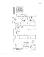
4. Refer to the appropriate tank configuration figure to check the tank configuration and
install the tape/cable piping and gaugeboard.
Complete the Anchor Bar Installation, Float Installation, Initial Lubrication, and Reassembly
sections of the previous procedure, Installation of Model 228 Inspection Hatch to Existing
Manhole Cover. See also the following section, Typical Auxiliary Equipment Installation.
Typical Auxiliary Equipment Installation
To install auxiliary equipment, an auxiliary elbow drive adapter kit (P/N 13-08821) is required.
The kit contains the English drive elbow (P/N BM4129) and the tape/cable combination (P/N
B7678-106). This has a sprocket sheave that is driven by the English tape/cable combination.
Usually this is installed on the outboard connection pipe elbow.
Note
The use of auxiliary units not manufactured or supplied by Varec will void any
Varec warranty and will relieve Varec of any obligation to service the product under war
-
ranty.
The perforated tape portion of the tape/cable combination must be seated on the sprocket
sheave throughout the travel of the indicator. The cable portion cannot drive an auxiliary
device. The cable portion attached to the pulley of the half-travel indicator may reach the
gaugeboard connector sheave before a vertical tank is empty if the gaugeboard is mounted
high on the tank.
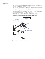
1. Remove the bolts, cover, and gasket from the elbow.
2. Remove the drive adapter flange bolts, washers, flange cap, and gasket.
3. Install the elbow on the indicator connector pipe.
4. Refer to the appropriate tank configuration installation procedures above and thread the
tape/cable through the elbow. The cable segment attaches to the gaugeboard indicator.
Содержание 6700
Страница 2: ......
Страница 24: ...Liquid Level Indicator 16 Installation and Operations Manual Figure 7 Cone Roof Tank Installation 12 50 318...
Страница 25: ...Installation Varec Inc 17 Figure 8 Half Travel Cone Roof Tank Installation 16 50 419...
Страница 31: ...Installation Varec Inc 23 Initial Lubrication Apply a light oil to the elbow and indicator sheaves...
Страница 37: ...Installation Varec Inc 29 Initial Lubrication Apply a light oil to the elbow and indicator sheaves...
Страница 39: ...Installation Varec Inc 31 Figure 15 Bolted Tank Installation 16 50 419...
Страница 51: ...Installation Varec Inc 43 Figure 20 Severe Service Cone Roof Tank Installation 12 50 318...
Страница 70: ...Liquid Level Indicator 62 Installation and Operations Manual...
Страница 73: ......

