


Liquid Level Indicator
14
Installation and Operations Manual
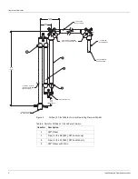
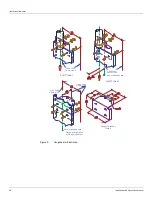
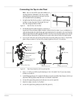
7. Center the base of a top cable anchor in its hole. Hold it plumb while welding it to the roof.
Do the same for the other top cable anchor.
8. Remove the housing nipple and cap from the top cable anchors and hang plumb lines from
them at the center to mark the position where the bottom cable anchor will be welded.
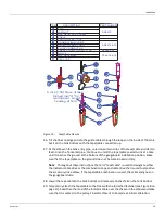
9. Mark the plumb bob string at the height of the tank bench mark. This will assure that the
plumb bob just touches the bottom, when the reference is made from the bench mark dis
-
tance to the bottom.
10. Hang a plumb line through the center of the top tape/cable pipe to the bottom to mark
the float center. This should be 8.50 inches [216 mm] at the bottom from each of the bot
-
tom cable anchor positions.
11. When the positioning has been checked, weld the bottom cable anchor into place.
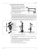
12. Thread the float guide cables into the tank through the top anchor fittings. Fasten them to
the bottom cable anchor with the furnished hardware. Thread the upper end of each guide
cable through the top anchor assembly. Hand tighten. Use the lock nut to lock the cable in
place, then tighten the adjustment nut, until the guide cable is tensioned by the spring.
Trim off excessive cable.
13. Replace the top anchor nipple and cap.
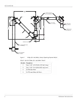
14. Apply appropriate pipe thread compound and install the sheave elbow on the vertical pipe
to the tank interior. Install a pipe union in the horizontal pipe run, in order that the elbows
can be easily removed, if necessary. Then install the horizontal pipe assembly into the tank
drop elbow. Adjust the length as needed to properly position the outboard elbow.
15. Install the outboard elbow on the horizontal pipe.
16. Apply pipe thread compound and screw the gaugeboard connector pipe into the outboard
elbow.
17. Remove the bolts, cover, and gasket from the outboard elbow and drop a plumb line
through the center.
18. Drop a chalk line from the top of the tank parallel with the plumb line and mark the chalk
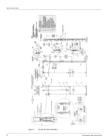
line on the tank wall. See Figure 7 on page 16.
19. Use the width of the gaugeboard (7.44 inches [189 mm]) at the bottom of the tank wall
and chalk register marks for the width as follows:
Full Travel Gaugeboard:
Board centered with chalked plumb line (see Figure 7 on page 16).
Half Travel Gaugeboard:
Board offset (1.03 inches [26.2 mm]) to the right of the chalked plumb line (see Figure 9
20. Do the same at the top of the tank.
21. Make chalk line marks between the top and bottom register mark to aid in keeping the
gaugeboard sections centered and parallel during installation.
22. Weld the gaugeboard support brackets into position. See Figure 7 and notice the relative
position of the top bracket. All other welds are seven feet below the previous weld, except
for the last one at the bottom of the tank, which is six inches [152 mm] above the grade
line.
23. Use the “U” bolt and nuts (see Figure 7) to attach the gaugeboard connector to the pipe.
The pipe should extend one inch [25.4 mm] below the “U” bolt.
Содержание 6700
Страница 2: ......
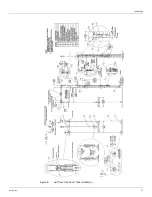
Страница 24: ...Liquid Level Indicator 16 Installation and Operations Manual Figure 7 Cone Roof Tank Installation 12 50 318...
Страница 25: ...Installation Varec Inc 17 Figure 8 Half Travel Cone Roof Tank Installation 16 50 419...
Страница 31: ...Installation Varec Inc 23 Initial Lubrication Apply a light oil to the elbow and indicator sheaves...
Страница 37: ...Installation Varec Inc 29 Initial Lubrication Apply a light oil to the elbow and indicator sheaves...
Страница 39: ...Installation Varec Inc 31 Figure 15 Bolted Tank Installation 16 50 419...
Страница 51: ...Installation Varec Inc 43 Figure 20 Severe Service Cone Roof Tank Installation 12 50 318...
Страница 70: ...Liquid Level Indicator 62 Installation and Operations Manual...
Страница 73: ......