


25
11. WARRANTY
This ventilation unit is a high quality product, built and packaged with care. The manufacturer warrants to the original
purchaser of its product, that such products will be free from defects for the period stated below, from date of original
purchase. For all units, the warranty covers parts only against any operational defect. This 5-year warranty is subject to
performance of the core maintenance according recommendations in this manual. The heat recovery core (HRV) has a
limited lifetime warranty, and the energy recovery core (ERV) has a 5-year warranty. If any defect should occur, we urge
you to read the user guide carefully. If the problem persists, observe the following rules:
RULES TO FOLLOW
If the unit is defective, contact your ventilation contractor (see address on your manual’s cover page). The contractor will
determine with you the reason for the defect, and if needed, do the replacement or repair. If ever it is impossible to reach
your ventilation contractor, call 1-800-567-3855 (in North America); the personnel will be pleased to give you the phone
number of a distributor or a service center near you.
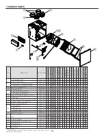
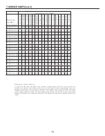
REPLACEMENT PARTS AND REPAIR
In order to ensure your ventilation unit remains in good working condition, you must use the manufacturer’s genuine
replacement parts only. The manufacturer’s genuine replacement parts are specially designed for each unit and are
manufactured to comply with all the applicable certi
fi
cation standards and maintain a high standard of safety. Any third
party replacement part used may cause serious damage and drastically reduce the performance level of your unit, which
will result in premature failing. The manufacturer also recommends that you contact a service depot certi
fi
ed by the
manufacturerfor all replacement parts and repair.
BILL OF PURCHASE
No replacement or repair covered by the warranty will be carried out unless the unit is accompanied by a copy of the
original bill of purchase. Please retain your original.
MISCELLANEOUS COSTS
In each case, the labor and shipping costs for the removal of a defective part and/or installation of a compliant part will
not be covered by the manufacturer.
CONDITIONS AND LIMITATIONS
These units are created for residential use only and must be used in a building as de
fi
ned below:
Building:
All structures zoned and/or erected for the act, process or art of human or animal habitation and/or the
storage or warehousing of goods.
Residential use:
Dwelling, lodging, suite: Building, or part of a building, intended to act as either the domicile to one or several
people which can include general sanitary, food consumption and rest facilities. Buildings of only one room
or a group of rooms including those occupied by a tenant or owner; comprise the lodgings, the individual
rooms of the motels, hotels, rooming/lodging houses, boarding/half-way/foster homes, dormitories, and
suites, as well as the stores and the business establishments constituted by only one room in a dwelling.
Commercial use:
Agricultural establishment, commercial establishment for assembly, care, or detention: Building or part
of a building that does not contain a dwelling, situated on land dedicated to agriculture or farming and
used primarily to shelter animals, or for the production, the storage or the treatment of agricultural or
horticultural products or animal food. Building or part of a building, used for the display or retail of goods,
professional or personal services, or commodities. Building, or part of a building used by persons gathering
for civic activities, religious or political assembly, tourism, educational/vocational training, recreation or the
consumption of food or drink. Building, or part of a building used to shelter persons of impaired physical
or psychological states, persons requiring palliative care or medical treatments, or persons for reasons out
of their control, cannot escape harm or threat of danger autonomously.
Industrial use:
Building, or part of a building, used for the assembly, the manufacture, the creation, the treatment, the
repair or the storage of products and combustible materials and that contain fuels that when ignited or
exploded in suf
fi
cient quantity may constitute a risk of
fi
re.
The above warranty applies to all cases where the damage is not a result of poor installation, improper use, mistreatment or
negligence, acts of God, or any other circumstances beyond the control of the manufacturer. Furthermore, the manufacturer
will not be held responsible for any bodily injury or damage to personal property or real estate, whether caused directly or
indirectly by the unit. This warranty supersedes all prior warranties.
Venmar Ventilation ULC, 550 Lemire Blvd., Drummondville, Québec, Canada J2C 7W9 venmar.ca / vanee.ca 800-567-3855


