


21
E
RROR
D
ESCRIPTION
S
OLUTION
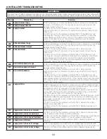
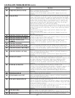
E26
Supply motor (drive over temp)
STEP 1: Validate if the air exchanger is exposed to ambient temperatures
within the operating limits (see p. 4)
If STEP 1 did not
fi
x the problem, perform STEP 2: Replace the electronic
assembly.
E32
Exhaust air
fl
ow
STEP 1: Unplug the unit. Perform a visual inspection of the exhaust damper
system. Clean
fi
lters, distribution registers and outside exhaust hood. Make
sure no non-return damper is installed in exhaust hood since it can freeze in
winter. Inspect ducting to ensure it is not squeezed or bent. Plug the unit.
If STEP 1 did not
fi
x the problem, perform STEP 2: Remove ducting of the
supply path. On the LCD screen, select MAX to check if the unit is able to
reach the selected
fl
ow. If so, review the ducting path.
If STEP 2 did not
fi
x the problem, perform STEP 3: On the LCD screen, select
the MIN and MAX
fl
ow setting values then reset the unit. MAX
fl
ow value will
display on the LCD screen. If MAX
fl
ow is above desired MAX
fl
ow, set MAX
and MIN
fl
ows.
If STEP 3 did not
fi
x the problem, perform STEP 4: Replace the exhaust
blower and repeat STEP 3.
If STEP 4 did not
fi
x the problem, perform STEP 5: Replace the electronic
assembly.
E33
Exhaust motor (drive over current)
STEP 1: Unplug/plug unit.
If STEP 1 did not
fi
x the problem, perform STEP 2: Remove core and clear the
ventilation wheel from any dirt or obstacles.
If STEP 2 did not
fi
x the problem, perform STEP 3: Disconnect J3 (red) and
connect a spare blower system. If it works, replace exhaust blower.
If STEP 3 did not
fi
x the problem, perform STEP 4: Replace the electronic
assembly.
E37
Exhaust motor (drive foc duration)
E38
Exhaust motor (drive speed
feedback)
E39
Exhaust motor (startup)
E34
Exhaust motor (drive over voltage)
STEP 1: Unplug/plug unit. Under and over voltage may be detected with
severe in-house power supply
fl
uctuation and stop the motor for protection.
If STEP 1 did not
fi
x the problem, perform STEP 2: Replace the electronic
assembly.
E35
Exhaust motor (drive under voltage)
E36
Exhaust motor (drive over temp)
STEP 1: Validate if the air exchanger is exposed to ambiant temperatures
within the operating limits (see p. 4)
If STEP 1 did not
fi
x the problem, perform STEP 2: Replace the electronic
assembly.
E40
Outside air thermistor
STEP 1: Check if thermistor is well connected in connector J7A.
If STEP 1 did not
fi
x the problem, perform STEP 2: Disconnect connector J7A
and check if the measured resistance (thermistor connector) is within
5 Kohms to 120 Kohms. If outside the range, replace the thermistor.
If STEP 2 did not
fi
x the problem, perform STEP 3: Replace the electronic
assembly.
E41
Distribution air thermistor
STEP 1: Check if thermistor is well connected in connector J7B.
If STEP 1 did not
fi
x the problem, perform STEP 2: Disconnect connector J7B
and check if the measured resistance (thermistor connector) is within
5 Kohms to 120 Kohms. If outside the range, replace the thermistor.
If STEP 2 did not
fi
x the problem, perform STEP 3: Replace the electronic
assembly.
E42
PCBA thermistor fault
STEP 1: Replace the electronic assembly.
E43
PCBA temperature over limit
STEP 1: Validate if the air exchanger is exposed to ambiant temperatures
within the operating limits (see p. 4)
If STEP 1 did not
fi
x the problem, perform STEP 2: Replace the electronic assembly.
E50
Wall control communication lost
STEP 1: Unplug unit, inspect wires, plug unit.
If STEP 1 did not
fi
x the problem, perform STEP 2: Remove wall control from
the wall installation and test with a short cable. If it works, bring a new cable
to the wall installation location.
If STEP 2 did not
fi
x the problem, perform STEP 3: Test the air exchanger with
a spare wall control. If it works, replace the wall control.
If STEP 3 did not
fi
x the problem, perform STEP 4: Replace the electronic
assembly.
E51
Wall control sensor
STEP 1: Unplug unit, inspect wires, plug unit.
If STEP 1 did not
fi
x the problem, perform STEP 2: Replace the wall control.
E60
Protection mode
STEP 1: Perform general inspection of the unit (dampers, core,
fi
lters).
8. INSTALLER’S TROUBLESHOOTING (
CONT
’
D
)


