Vanair Reliant RS45 Скачать руководство пользователя страница 17

RELIANT RS45 AIR COMPRESSOR

SECTION 3: INSTALLATION

090126-OP_r0 (JAN-2018)

PAGE - 9

VANAIR MANUFACTURING, INC.

(844) VAN-SERV • www.vanair.com

3.4.2  HYDRAULIC OIL RESERVOIR

3.4.2.1   DETERMINING RESERVOIR SIZE

In a conventional hydraulic system, minimum
tank size, in gallons, should be equal to the
maximum GPM flow rate, times two (x 2).

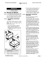
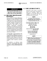
3.4.2.2    DETERMINING RESERVOIR 

SHAPE

The  reservoir  structure  should  be  tall  and
narrow  rather  than  shallow  and  broad
(

Figure 3-1

).  A  tall,  narrow  tank  is

recommended because:

1.  The oil level is well above suction line 

opening, avoiding the  possibility of 
drawing air into the pump due to a vortex 
or “whirlpool” effect within the tank during 
operation flow.

2.  Allows for better oil level tolerance level 

of the system if vehicle operates at an 
unusual (slightly off level) vehicle angle.

3.  To keep return flow well below the 

surface so it does not break the surface 
and cause aeration (cavitation) of the oil.

3.4.2.3   MANDATORY RESERVOIR 

FEATURES

• The reservoir should incorporate the 

following design features:

• In terms of location of the reservoir tank 

within the hydraulic system, note that the 

hydraulic pump’s inlet line (suction line 

out 

from

 the reservoir 

to

 the pump) 

should be located near the bottom of the 

tank, well below the oil level. The suction 

line should protrude a minimum of two 

(2”) inches into the reservoir to keep it 

away from potential contaminant surface 

buildup.

• A baffle or baffles should be included to 

prevent sloshing, or centrifugal motion of 

the oil; the goal is to break up direct flow 

of the oil from the return point to the 

suction point. This allows for the cooling 

action contact with the tanks’ inner 

surfaces, and promote separation of any 

air or contaminants that interact with the 

flowing oil.

• An ideal baffle design would position 

several (but not too many) baffles to 

promote an ‘S’ shape flow within the 

reservoir, as viewed from above. The 

area of the end gaps should be at least 

twice the area of the suction line 

diameter.

• A drain port with plug, situated at the 

lowest point of the reservoir, is needed to 

assure complete draining. It should be 

installed using an adapter or housing 

which does not protrude above the inner 

surface of the floor of the tank. It should 

be visible and  accessible for removal, 

with sufficient space available for 

catching the waste oil.

• If the return line entrance to the tank is 

located near the top, it should be 

extended downward within the tank to 

minimize foaming and aeration of the 

circulating oil. This extends oil integrity, 

which in turn helps to maintain system 

performance and reliability.

IMPORTANT

Use only a filter that is specifically intended 

for hydraulic systems.

KEY

DESCRIPTION

A

PREFERRED SHAPE: 

TALL AND NARROW

B

SHAPE TO AVOID:

 BROAD AND SHALLOW

Figure 3-1: Reservoir Design Shape

A

B

Содержание Reliant RS45

Страница 1: ...uthorized modifications to the system components WILL VOID THE WARRANTY Always inform Vanair Manufacturing Inc before beginning any changes to the RS45 system KEEP THE MANUAL WITH THE VEHICLE NOTE Thi...

Страница 2: ...e and use by commercial industrial users and persons trained and experienced in the use and maintenance of industrial equipment In the event of a warranty claim covered by this Limited Warranty the ex...

Страница 3: ...1 SAFETY 1 1 1 GENERAL INFORMATION 1 1 2 DANGERS WARNINGS CAUTIONS AND NOTES 1 1 2 1 DANGERS 1 1 2 2 WARNINGS 1 1 2 3 CAUTIONS 2 1 2 4 NOTES 3 1 3 SAFETY DECALS 3 1 4 DISPOSING OF MACHINE FLUIDS 3 SE...

Страница 4: ...1 3 5 4 SERVICE CONNECTIONS 11 3 5 5 ELECTRICAL CONNECTIONS 11 3 5 6 HYDRAULIC SUPPLY CIRCUIT 11 3 5 7 ROUTING 11 Figure 3 3A Dimension Diagram RS45 Open Center Without Thermal Valve 12 Figure 3 3B Di...

Страница 5: ...SYSTEMS 30 5 4 6 PRESSURE RELIEF VALVE 31 5 4 7 REPLACING THE DRIVE COUPLING 31 5 4 7 1 REPLACING THE DRIVE COUPLING ELEMENT 32 5 4 7 2 COUPLING ASSEMBLY 32 5 4 7 3 HUB ALIGNMENT CHECK 33 5 4 7 4 COUP...

Страница 6: ...VE ASSEMBLY CLOSED CENTER 64 7 12 DISPLAY AND CONTROLLER ASSEMBLY 65 7 13 HYDRAULIC MANIFOLD ASSEMBLY OPEN CENTER 66 7 14 HYDRAULIC MANIFOLD ASSEMBLY CLOSED CENTER 67 7 15 DECALS PART 1 OF 2 IDENTIFIC...

Страница 7: ...applicable temperature and pressure readings and also the number of operational hours available Note that the above information will also need to be included on the Return Material Authorization Form...

Страница 8: ...Day Second Day VANAIR WILL NEVER ACCEPT ANY INVOICES FOR PARTS RETURNED ANY PARTS RETURNED VIA INVOICE WILL BE RETURNED FREIGHT COLLECT NO PARTS ARE TO BE RETURNED FREIGHT COLLECT Vanair Mfg Inc striv...

Страница 9: ...r touch electrical wires or components while the machine is operating They can be sources of electrical shock 1 2 2 WARNINGS DO NOT EVER use this compressor as a breathing air source Vanair disclaims...

Страница 10: ...p causing injuries or damage DO NOT use tools hoses or equipment that have maximum ratings below that of this compressor Keep metal tools and other conductive objects away from live electrical compone...

Страница 11: ...ocated near system components that can present a hazard to operators or service personnel All pertinent decals listed in Section 7 15 Decals are located near a component which is subject to respect in...

Страница 12: ...SECTION 1 SAFETY RELIANT RS45 AIR COMPRESSOR PAGE 4 090126 OP_r0 JAN 2018 BLANK PAGE VANAIR MANUFACTURING INC 800 526 8817 www vanair com...

Страница 13: ...Rotary Screw Compressor oil tank capacity 4 U S Quarts 3 7L Compressor overheating protection Shut Down at 240 F Air inlet system Dry type Single Stage Filter Drive coupling Direct Drive Flex Jaw Coup...

Страница 14: ...clearances refer to Figure 3 2 Minimum Installation Clearances in Section 3 Installation NOTE Specifications are subject to change without notice TABLE 2B PRIME LUBRICANT CHARACTERISTICS Viscosity 17...

Страница 15: ...en damaged during shipment WARNING Before performing maintenance or repair operations on the compressor ensure that all power has been removed and locked out to prevent accidental application DO NOT a...

Страница 16: ...ic load is necessary when compressor is running The duty cycle and ambient operating temperatures Other hydraulic equipment which may share that same hydraulic supply system Vanair recommends a dedica...

Страница 17: ...de a minimum of two 2 inches into the reservoir to keep it away from potential contaminant surface buildup A baffle or baffles should be included to prevent sloshing or centrifugal motion of the oil t...

Страница 18: ...stem oil when adding new oil Return line diffuser splash plate reduces velocity of oil flow before return oil stream merges with the main reservoir oil volume A reservoir heater For those systems that...

Страница 19: ...e unit in the base frame 3 5 5 ELECTRICAL CONNECTIONS Refer to Figure 3 3A through 3 3D This system is offered with either 12V DC or 24V DC circuits 3 5 6 HYDRAULIC SUPPLY CIRCUIT Refer to the hydraul...

Страница 20: ...LIC MOTOR OIL FILL FILTER OIL 21 00 OIL DRAIN HOSE 22 81 DISPLAY MODULE TO MOTOR OIL SUPPLY HYDRAULIC DISCHARGE AIR SCALE 3 16 VIEW A A A A PARTS REMOVED FOR CLARITY CLEARANCE HOOD 19 82 REMOVED FOR C...

Страница 21: ...SSEMBLY THERMAL VALVE 21 00 CASE DRAIN HYDRAULIC MOTOR SCALE 3 16 VIEW A A A A TO MOTOR OIL SUPPLY HYDRAULIC DISCHARGE AIR OIL DRAIN COMPRESSOR OIL DRAIN HOSE AIR FILTER INTAKE REMOVED FOR CLARITY ACC...

Страница 22: ...SUPPLY HYDRAULIC CASE DRAIN HYDRAULIC MOTOR TO TANK OIL RETURN HYDRAULIC OIL FILL OIL DRAIN HOSE SCALE 3 16 VIEW A A A A DISCHARGE AIR OIL DRAIN COMPRESSOR 22 81 1 52 33 60 2 25 5 13 AIR FILTER INTAKE...

Страница 23: ...IN HOSE AIR FILTER INTAKE REMOVED FOR CLARITY ACCESS PANEL 1 52 33 60 2 25 5 13 CLEARANCE HOOD 19 82 19 25 27 00 4x 0 56 PARTS REMOVED FOR CLARITY LOAD SENSE TO MOTOR OIL SUPPLY HYDRAULIC CASE DRAIN H...

Страница 24: ...SECTION 3 INSTALLATION RELIANT RS45 AIR COMPRESSOR PAGE 16 090126 OP_r0 JAN 2018 BLANK PAGE VANAIR MANUFACTURING INC 844 VAN SERV www vanair com...

Страница 25: ...ature Screen Continuously monitors service line discharge temperature Will activate shut down if over temperature occurs Hour Meter Screen Indicates accumulated hours of operation for planning and log...

Страница 26: ...R x 2 S LIFTING BAIL F THERMAL VALVE ASSEMBLY I T COMPRESSOR OIL FILTER ELEMENT G AIR INLET CONTROL SOLENOID U COMPRESSOR OIL FILL PORT CAP H COMPRESSOR SIGHT GLASS V CONTROLLER DISPLAY PANEL J COMPRE...

Страница 27: ...the compressor and start producing air 8 Check for leaks 9 Refer to Figure 4 5 Press the START button on the Controller and wait for the Main Screen default is the Pressure Screen Check pressure and t...

Страница 28: ...ED B OIL FILL PORT cut away view with cap removed C HIGH LEVEL MARK top of thread port D LOW LEVEL MARK bottom thread of port I E ACCEPTABLE OIL LEVEL RANGE I When level is low add oil as needed NOTE...

Страница 29: ...ressure Screen It shows the current pressure status of the machine Pressing ESC from any other screen will bring this screen up 2 SETTING ADJUSTMENT DISPLAY SCREEN This screen shows the preset cut in...

Страница 30: ...ons for operating parameters 4 3 5 EXTREME CONDITION OPERATION When operating in extreme hot or cold conditions extra attention should be given to any indications that could lead to a serious problem...

Страница 31: ...t operating the compressor package in a severe environment may require more frequent service intervals than prescribed in the periodic maintenance schedule WARNING Follow all applicable safety recomme...

Страница 32: ...and or replacing non routine parts For assistance in obtaining routine maintenance or replacement parts consult Section 7 1 Parts Ordering Procedure and Table 7A Recommended Spare Parts List 5 3 REPLA...

Страница 33: ...ea between the bottom of the threaded portion of the oil fill port and the edge of the oil fill port rim AT SIGHT GLASS lies between 1 4 and 3 4 intervals of the visible glass area both give the same...

Страница 34: ...SS lies between 1 4 and 3 4 intervals of the visible glass area both give the same level of the sump PROCEDURE CONTINUED ON NEXT PAGE Continued on next page TABLE 5A ROUTINE MAINTENANCE SCHEDULE WARNI...

Страница 35: ...it no KIT1359 For compressor air filter replacement element only order filter no 264469 Air filter is serviced at the 500 service intervals annually or if prompted by the control panel indication In e...

Страница 36: ...n to clean it out The fan may need to be removed from the shroud in order to reach parts of the core Do not use high pressure air or a pressure washer TABLE 5A ROUTINE MAINTENANCE SCHEDULE WARNING Bef...

Страница 37: ...In the case where the drive coupling element needs to be serviced refer to Section 5 4 7 alignment is automatically achieved by securing the motor to the unit via the motor adapter However in the case...

Страница 38: ...Parts Department to obtain a replacement valve 5 4 4 SERVICING THE SYSTEM CIRCUIT BREAKER FUSES AND RELAY Consult Figure 5 3 for the locations of the fuses and circuit breaker Vanair recommends using...

Страница 39: ...ance Shut down machine relieve all system pressure and lock out all power as per the Safety Section of this manual NOTE THAT THE SYSTEM CAN BE STARTED REMOTELY Always clearly tag the start up instrume...

Страница 40: ...rotated slightly by hand to achieve coupling and element alignment 7 Re install the two 3 8 capscrews and lock washer sets to secure the motor to the motor mount 8 Before torquing the bolts perform an...

Страница 41: ...0 apart the maximum gap should not exceed the offset limit listed in Figure 5 5 5 4 7 3 HUB ALIGNMENT CHECK To ensure alignment refer to Figure 5 5 and the following procedure 1 Place a straight edge...

Страница 42: ...of deterioration such as visible surface cracks stiffness or discoloration 5 4 8 2 LONG TERM STORAGE Cover the unit with a tarp or plastic to prevent the accumulation of dust but leave the bottom open...

Страница 43: ...ly noticeable by discoloration or a burnt odor Should the problem persist after making the recommended check consult your nearest Vanair representative or the Vanair Service Department Make sure to ha...

Страница 44: ...or over pressures Defective pressure transducer Replace pressure transducer Contact factory service department Inlet valve stuck open Free or replace valve Solenoid valve not energized or faulty Check...

Страница 45: ...er shutdown Solenoid valve stuck Should be no power to solenoid valve Replace solenoid valve Leak back from air line Check minimum pressure valve for leaks Compressor stalls Insufficient hydraulic sys...

Страница 46: ...pump fluid may be too cold Air is present in fluid Regard any or all of the following Tighten leaking connections fill reservoir to proper level with rare exception all return lines should be below f...

Страница 47: ...essure gauge and adjust to correct pressure keep at least 125 PSI difference between valve settings Load is excessive Align unit and check condition of seals and bearings locate and correct mechanical...

Страница 48: ...cooling system is faulty Clean cooler and or cooler strainer replace cooler control valve repair or replace cooler Pump valve motor cylinder or other component is are worn Overhaul or replace item as...

Страница 49: ...ylinder or other component is are worn Overhaul or replace item as noted Flow is excessive Flow control is set too high Adjust as necessary Yoke actuating device is inoperative variable displacement p...

Страница 50: ...ting device is inoperative variable displacement pumps Overhaul or replace yoke actuating device Pressure reducing relief or unloading valve is worn or damaged Overhaul or replace as necessary HYDRAUL...

Страница 51: ...low Moves Erratically Pressure is erratic Refer to information under INCORRECT PRESSURE in this guide Air is present in fluid Refer to information under EXCESSIVE NOISE in this guide Machine integral...

Страница 52: ...HYDRAULIC DRIVE SYSTEM FAULTY OPERATION CONTINUED Hydraulic Flow Moves Excessively continued Servo amplifier is out of adjustment or malfunctioning Adjust repair or replace Work load is overriding Ad...

Страница 53: ...rts always indicate the Serial Number of the machine package This can be obtained from the Bill of Lading for the machine package or from the compressor unit serial number plate See Figure 7 1 for loc...

Страница 54: ...ter no 264471 III 500 hour maintenance kit consists of one 1 gallons of Vanair Vanguard Compressor Oil no 264626 1GAL compressor oil filter no 264471 air filter no 264469 and separator filter no 26447...

Страница 55: ...RELIANT RS45 AIR COMPRESSOR SECTION 7 ILLUSTRATED PARTS LIST 090126 OP_r0 JAN 2018 PAGE 47 VANAIR MANUFACTURING INC 844 VAN SERV www vanair com NOTES...

Страница 56: ...OTES 1 USE LOCTITE 567 THREAD SEALANT WITH PTFE OR EQUIVALENT SEALANT ON ALL MALE PIPE THREADS 2 LUBRICATE ALL ELASTOMERIC SEALS GASKETS O RINGS BEFORE TIGHTENING 3 ALL BOLTS TO BE TORQUED TO THEIR RE...

Страница 57: ...825506 198 7 7 ADAPTER M JIC 1 2 x BSPP 3 8 264312 007 2 22 CAPSCREW HEX 8mm 1 25 x 30 828008 030 4 8 COMPR PART VANAIR 31 EMC 12VDC STD SHAFT 269761 1 23 CAPSCREW HEX 10mm 1 5 x 25 828010 025 4 9 VAL...

Страница 58: ...EQUIVALENT SEALANT ON ALL MALE PIPE THREADS 2 LUBRICATE ALL ELASTOMERIC SEALS GASKETS O RINGS BEFORE TIGHTENING 3 ALL BOLTS TO BE TORQUED TO THEIR RESPECTIVE SAE TORQUE SPECIFICATIONS FOR THEIR GRADE...

Страница 59: ...8 263748 001 2 20 NUT HEX LOCKING 3 8 16 825506 198 7 7 ADAPTER FEMALE PIPE x BSPP 1 4 263748 004 1 21 CAPSCREW HEX 8mm 1 25 x 30 828008 030 4 8 ADAPTER M JIC 1 2 x BSPP 3 8 264312 007 2 22 CAPSCREW H...

Страница 60: ...LER MOUNTING 277426 AL 9 10 FOAM SOUND INSULATION COOLER SHROUD 278201 008 10 11 SPACER RS45 COOLER 278289 4 12 NUT HEX FLANGE 5 16 18 825305 283 8 13 NUT HEX LOCKING 1 4 20 825504 145 1 14 CAPSCREW H...

Страница 61: ...8289 4 12 NUT HEX LOCKING 1 4 20 825504 145 1 13 CAPSCREW HEX GR5 1 4 20 x 0 75 829104 075 1 14 CAPSCREW HEX GR8 1 4 20 x 0 75 829404 075 4 15 SCREW SER WASH 5 16 18 x 0 75 829705 075 12 16 WASHER FLA...

Страница 62: ...Y DRAWING STANDARD NOTES 1 USE LOCTITE 567 THREAD SEALANT WITH PTFE OR EQUIVALENT SEALANT ON ALL MALE PIPE THREADS 2 LUBRICATE ALL ELASTOMERIC SEALS GASKETS O RINGS BEFORE TIGHTENING 3 ALL BOLTS TO BE...

Страница 63: ...PANEL 2 00 INCH ID CLEAR 278418 1 6 PANEL HOOD RS45 277399 1 21 NUT HEX FLANGE 5 16 18 825305 283 2 7 PANEL FRONT 277400 1 22 NUT HEX LOCKING 8 32 825501 070 2 8 PANEL RIGHT 277401 1 23 NUT HEX LOCKIN...

Страница 64: ...0126 OP_r0 JAN 2018 VANAIR MANUFACTURING INC 844 VAN SERV www vanair com 1 ORIENTATION OF PARTS MAY BE DIFFERENT THAN ACTUAL MACHINE FOR VISUAL PURPOSES 2 SOME PARTS MAY BE REMOVED FOR VISUAL PURPOSES...

Страница 65: ...JIC 08 266214 1 2 HOSE HYD OIL COOLER RETURN 277509 1 3 HOSE HYD OIL COOLER SUPPLY 277512 1 4 HOSE HYD MOTOR CASE DRAIN 277513 1 5 HOSE COMPR OIL DRAIN 277514 1 6 HOSE DISCHARGE AIR 277518 1 7 HOSE EX...

Страница 66: ...26 OP_r0 JAN 2018 VANAIR MANUFACTURING INC 844 VAN SERV www vanair com 7 8 HOSE TUBE ASSEMBLY OPEN CENTER WITH THERMAL VALVE 6120301ID_r1 NOTES 1 ORIENTATION OF FITTINGS MAY BE DIFFERENT FROM ACUAL MA...

Страница 67: ...HYD MOTOR CASE DRAIN 277513 1 4 HOSE COMPR OIL DRAIN 277514 1 5 HOSE DISCHARGE AIR 277518 1 6 HOSE HYDR OIL RETURN 277633 1 7 TUBE COOLER TO THERMAL VALVE RETURN 277635 1 8 HOSE EXTERNAL COMPR OIL DR...

Страница 68: ...6 OP_r0 JAN 2018 VANAIR MANUFACTURING INC 844 VAN SERV www vanair com 7 9 HOSE TUBE ASSEMBLY CLOSED CENTER NO THERMAL VALVE 6120305ID_r1 NOTES 1 ORIENTATION OF FITTINGS MAY BE DIFFERENT FROM ACTUAL MA...

Страница 69: ...JIC 08 266214 1 2 HOSE LOAD SENSE 277496 1 3 HOSE HYD OIL COOLER RETURN 277509 1 4 HOSE HYD MOTOR CASE DRAIN 277513 1 5 HOSE COMPR OIL DRAIN 277514 1 6 HOSE DISCHARGE AIR 277518 1 7 HOSE EXTERNAL COMP...

Страница 70: ...OP_r0 JAN 2018 VANAIR MANUFACTURING INC 844 VAN SERV www vanair com 7 10 HOSE TUBE ASSEMBLY CLOSED CENTER WITH THERMAL VALVE 6120304ID_r1 NOTES 1 ORIENTATION OF FITTINGS MAY BE DIFFERENT FROM ACTUAL...

Страница 71: ...E LOAD SENSE 277496 1 4 HOSE HYD MOTOR CASE DRAIN 277513 1 5 HOSE COMPR OIL DRAIN 277514 1 6 HOSE DISCHARGE AIR 277518 1 7 HOSE HYDR OIL RETURN 277633 1 8 TUBE COOLER TO THERMAL VLV RETURN 277635 1 9...

Страница 72: ...IC x 16 MSAE 260403 113 1 3 VALVE THERMAL BYPASS 1 SAE 50PSI 100 DEG 274255 1 NS HARNESS COLD WEATHER HEATER PADS 278541 1 PLEASE NOTE WHEN ORDERING PARTS INDICATE MACHINE SERIAL NUMBER ASSEMBLY DRAWI...

Страница 73: ...RIPTION PART NUMBER QTY 1 DISPLAY COLOR 2 8 INCH 276319 1 2 PLUG HOLE 3 8 DIA WH 277184 2 3 BRACKET MOUNTING 2 8 INCH DISPLAY 277665 1 4 COVER BASIC CONTROLLER 277666 1 5 SCREW MACHINE 6 32 X 5 8 8316...

Страница 74: ...ONNECTOR 278370 1 11 VALVE CHECK 3 4 MSAE x 3 4 MJIC 85 PSI CRACKING 278457 1 12 NUT HEX LOCKING 5 16 18 825505 166 2 13 CAPSCREW HEX GR5 5 16 18 x 3 829105 300 2 14 SCREW SER WASH 1 4 20 x 0 75 82970...

Страница 75: ...16 UNF 269751 1 10 BRACKET HYDRAULIC RETURN 277429 1 11 BRACKET AIR DISCHARGE 277974 1 12 NUT HEX LOCKING 3 8 16 825506 198 2 13 CAPSCREW GR8 3 8 16 X 3 829406 300 2 14 SCREW SER WASH 5 16 18 x 0 75...

Страница 76: ...R SECTION 7 ILLUSTRATED PARTS LIST PAGE 68 090126 OP_r0 JAN 2018 VANAIR MANUFACTURING INC 844 VAN SERV www vanair com 1 2 9 10 4 13 15 17 3 6 7 12 8 5 11 14 18 21 23 22 20A 20B 16A 16B 19 7 15 DECALS...

Страница 77: ...7 DECAL WARNING AIR 261886 1 20A DECAL LABEL 12V DC II 275974 1 8 DECAL WARNING ROTATING PARTS 264374 1 20B DECAL LABEL 24V DC II 275975 1 9 DECAL WARNING CONNECT AIR HOSE 261885 1 21 DECAL COMPR FLU...

Страница 78: ...JAN 2018 VANAIR MANUFACTURING INC 844 VAN SERV www vanair com 2 1 3 9 10 11 14 17 12 13 19 22 20A or 20B 18 21 23B 23A 16B 15 16 16 5 6 7 4 8 7 15 DECALS PART 2 OF 2 LOCATIONS WARNING DO NOT REMOVE OR...

Страница 79: ...L ROTATION HYDRAULIC SUPPLY HYDRAULIC SUPPLY HYDRAULIC RETURN PRESSURE COMPENSATOR ON HYDRAULIC PUMP PRESSURE COMPENSATOR ON HYDRAULIC PUMP TRUCK SYSTEM PRESSURE RETURN MACHINE END PANEL FLOW CONTROL...

Страница 80: ...OW CONTROL VALVE SOLENOID VALVE TRUCK SYSTEM MACHINE HYDRAULICS LOAD SENSE HYDRAULIC OIL COOLER CASE DRAIN HYDRAULIC MOTOR THERMAL VALVE DIRECTION HYDRAULIC OIL HYDRAULIC SUPPLY HYDRAULIC SUPPLY HYDRA...

Страница 81: ...AN SERV www vanair com DIRECTION HYDRAULIC OIL RESERVOIR PUMP TRUCK SYSTEM FILTER PRESSURE RETURN MACHINE END PANEL SOLENOID VALVE RELIEF VALVE P T A B 85PSI CRACKING TRUCK SYSTEM MACHINE HYDRAULICS H...

Страница 82: ...ir com P T A B 85PSI CRACKING DIRECTION HYDRAULIC OIL RESERVOIR PUMP TRUCK SYSTEM FILTER PRESSURE RETURN MACHINE END PANEL SOLENOID VALVE RELIEF VALVE TRUCK SYSTEM MACHINE HYDRAULICS HYDRAULIC OIL COO...

Страница 83: ...TRANSDUCER 1 BLOW DOWN LIVE FEED MUST BE CONNECTED TO A TERMINAL ON CONNECTOR OF FAN AIR SOLENOID TEMPERATURE THERMISTOR PIN A PIN B FAN MOTOR PRESSURE TRANSDUCER 2 LINE P N1 VBBS VBB1 VBB2 GND CAN1H...

Страница 84: ...er than twisting 4 Use elbows or other adapters as necessary to eliminate excess hose length and to insure neater installation for easier maintenance 2 Ample bend radius should be provided to avoid co...

Страница 85: ...ILLUSTRATED PARTS LIST 090126 OP_r0 JAN 2018 PAGE 77 VANAIR MANUFACTURING INC 844 VAN SERV www vanair com TABLE 7C MAINTENANCE TRACKING LOG DATE DESCRIPTION OF MAINTENANCE PART S REPLACED DATE DESCRI...

Страница 86: ...BLANK PAGE...

Страница 87: ...BLANK PAGE...

Страница 88: ...ge Without Prior Notice 051598 051603 051608 051612 Vanair Manufacturing Inc 10896 West 300 North Michigan City IN 46360 Phone 219 879 5100 844 VAN SERV 844 826 7378 Service Fax 219 879 5335 Parts Fax...

Отзывы: