


© July 2017 Van Essen Instruments. All rights reserved
.
3
2.2
Installation
Connect the Diver-MOD to a Diver through a Diver communication cable (AS2xxx). Connect the Diver
communication cable to the Diver-MOD by attaching it to the M12 connector.
Connect the PC or PLC to the Diver-MOD using a 4-conductor cable. The 4-conductors are for
5 to 12-volt power supply
ground
RS485-A
RS485B
Feed the Modbus communication and power supply cable into the enclosure through the cable
gland and connect the wires as depicted in Figure 3. The cable gland provides an IP67 sealing for
Modbus cables with a diameter from 3.5 to 7 mm.
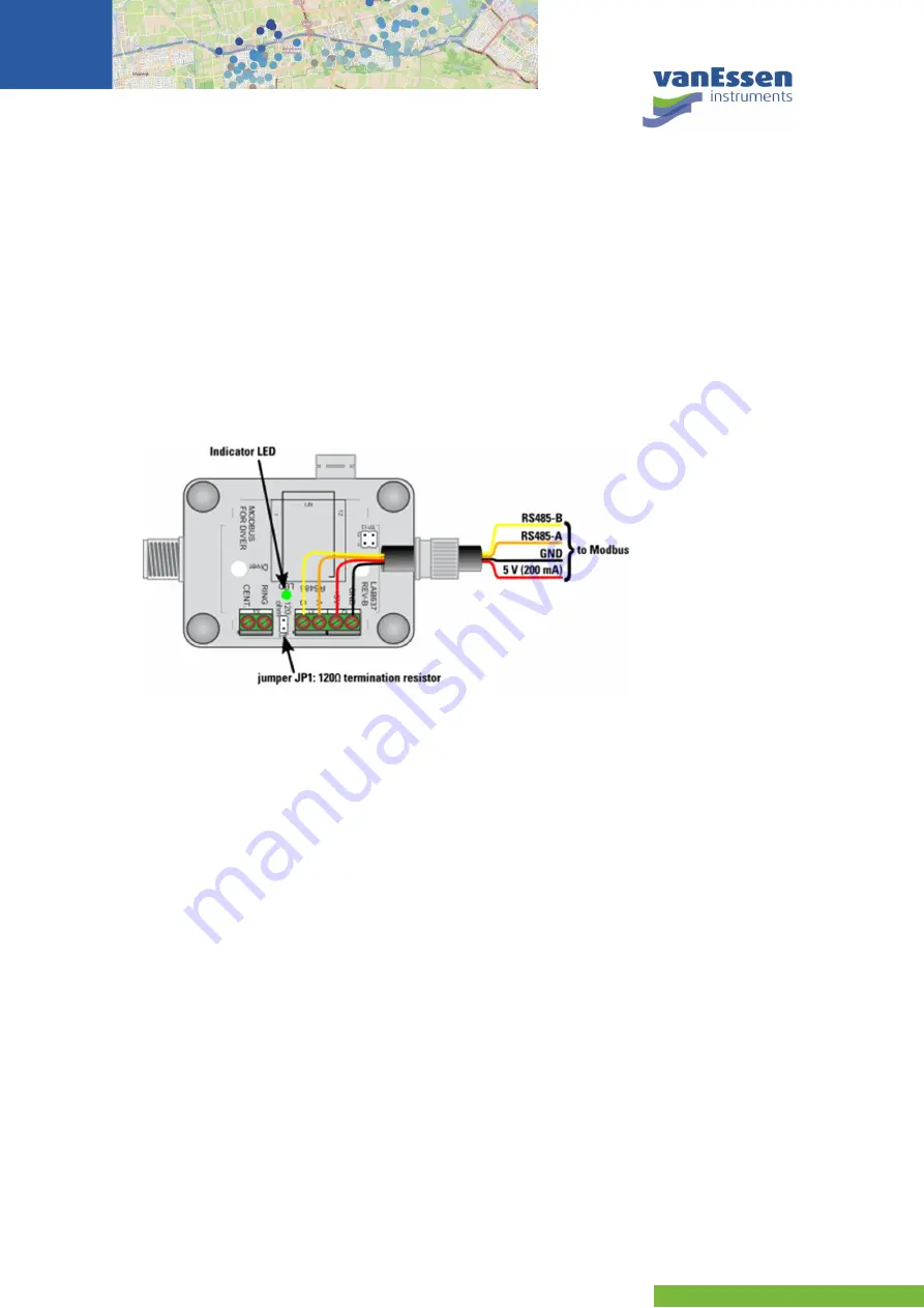
Figure 3
Diver-MOD connection to Modbus/RTU (cable colors may vary).
The Diver-MOD must be externally powered with +5VDC or +12VDC (4.75 Volt to 13.5 Volt). During
communication the peak current is 50 mA and the effective current is 20 mA. The stand-by current of
the Diver-MOD is 2 mA.
If the Diver-MOD is the last device in the RS485 network, the A and B line should be terminated with a
120 termination resistor. This can be done by placing jumper JP1, see Figure 3.
There is one signal indicator (LED) which will light up briefly when the Diver-MOD is powered on. In
addition, the LED will blink when there is activity on the RS485 communication line. When the Diver-
MOD is in standby, the LED will be off.
2.3
Configuration
Diver-MOD is designed to communicate on a Modbus network using RTU (Remote Terminal Unit)
mode. The ASCII (American Standard Code for Information Interchange) mode is
not
supported by
the Diver-MOD.
The default serial settings are 9,600 bps, no parity and 1 stop bit. If the serial settings are changed by
Modbus function codes, the changes take place after repowering.
The default Diver-MOD address is 1. If the slave address is changed by Modbus function codes, the
change takes place immediately.