3
B
A
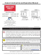
Mantel
23”
(584 mm)
7-1/2”
(191 mm)
25-1/8”
(638 mm)
27-1/2” (699 mm)
14”
(356 mm)
17-7/8”
(454 mm)
Ø 6-5/8”
venting
Supplied with
top vent; field
convertible to
rear vent
Centre of vent
28-1/2 ” (724 mm)
x
Gas inlet position
3/8” fem. NPT
x
2”
(52 mm)
minimum
Gas line connection point
3/8” NPT FEMALE at valve
Sidewall
17-7/8”
(454 mm)
4”
(102 mm)
2” (52 mm)
minimum
Ø 6-5/8”
venting
Suggested gas line
access point through wall.
Route to avoid optional fan.
Pipe supplied with
engine (see engine
manual p. 18)
x
Mantel / shelf clearances
Mantel
Depth ‘A’
0–1
[0–26]
2–5
[51–127]
6–18
[152–457]
19–24
[483–610]
Mantel
Height ‘B’
34
[864]
36
[914]
38
[965]
42
[1067]
Corner clearances
Min. 2”
between
combustible
wall and
stove
Min. 2” between
combustible wall
and stove
32-1/2” minimum
42
” minimum
26” m
axim
um
Alcove clearances
inches [mm]
Dimensions & Clearances
For installation purposes, diagrams
represented by the arched front